
Electrically small planar antennas with inductively coupled feed

a technology of inductive coupling and electric small antenna, which is applied in the direction of antennas, antenna details, basic electric elements, etc., can solve the problems of difficult redesign of complex structures, difficult antenna fabrication, and complex structures of existing designs for electrically small antennas

Active Publication Date: 2005-03-17
INTELLECTUAL VENTURES HLDG 40
View PDF9 Cites 7 Cited by
  • Summary
  • Abstract
  • Description
  • Claims
  • Application Information

AI Technical Summary

Problems solved by technology

Existing designs for electrically small antennas typically have complicated structures.
Complicated structures may make antenna fabrication difficult.
Complicated structures may also be difficult to redesign to meet different operating frequencies.
The small input resistance may cause difficulty in matching the antenna to the associated radio frequency (RF) system.
However, matching circuits may add to the size, loss, complexity and / or cost of the system.

Method used


Image

  • Electrically small planar antennas with inductively coupled feed
  • Electrically small planar antennas with inductively coupled feed
  • Electrically small planar antennas with inductively coupled feed

Examples


Embodiment Construction

disclosed herein generally relate to methods of designing antennas and antennas designed by those methods. In particular, embodiments relate to antennas with inductively coupled feed.

2. Description of Related Art

Electrically small antennas may include antennas with a size about 10% of the operating wavelength of the antenna or less (e.g., 5% of the operating wavelength). Existing designs for electrically small antennas typically have complicated structures. For example, Goubau (reference 6), Dobbins et al. (reference 7) and Foltz et al. (reference 8) each disclose relatively complex antenna designs. Complicated structures may make antenna fabrication difficult. Complicated structures may also be difficult to redesign to meet different operating frequencies. A concern with many electrically small antennas is that the input resistance of such antennas may be relatively small. The small input resistance may cause difficulty in matching the antenna to the associated radio frequency (...


PUM


Abstract

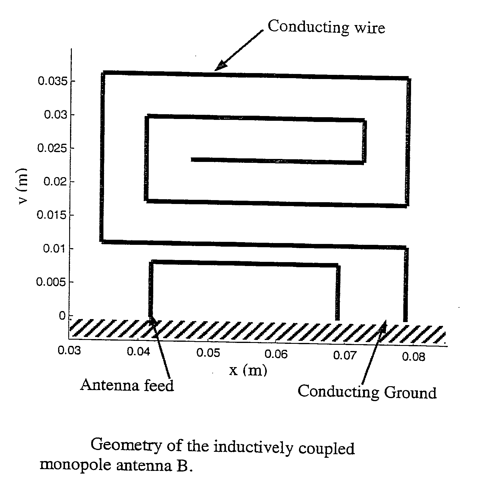
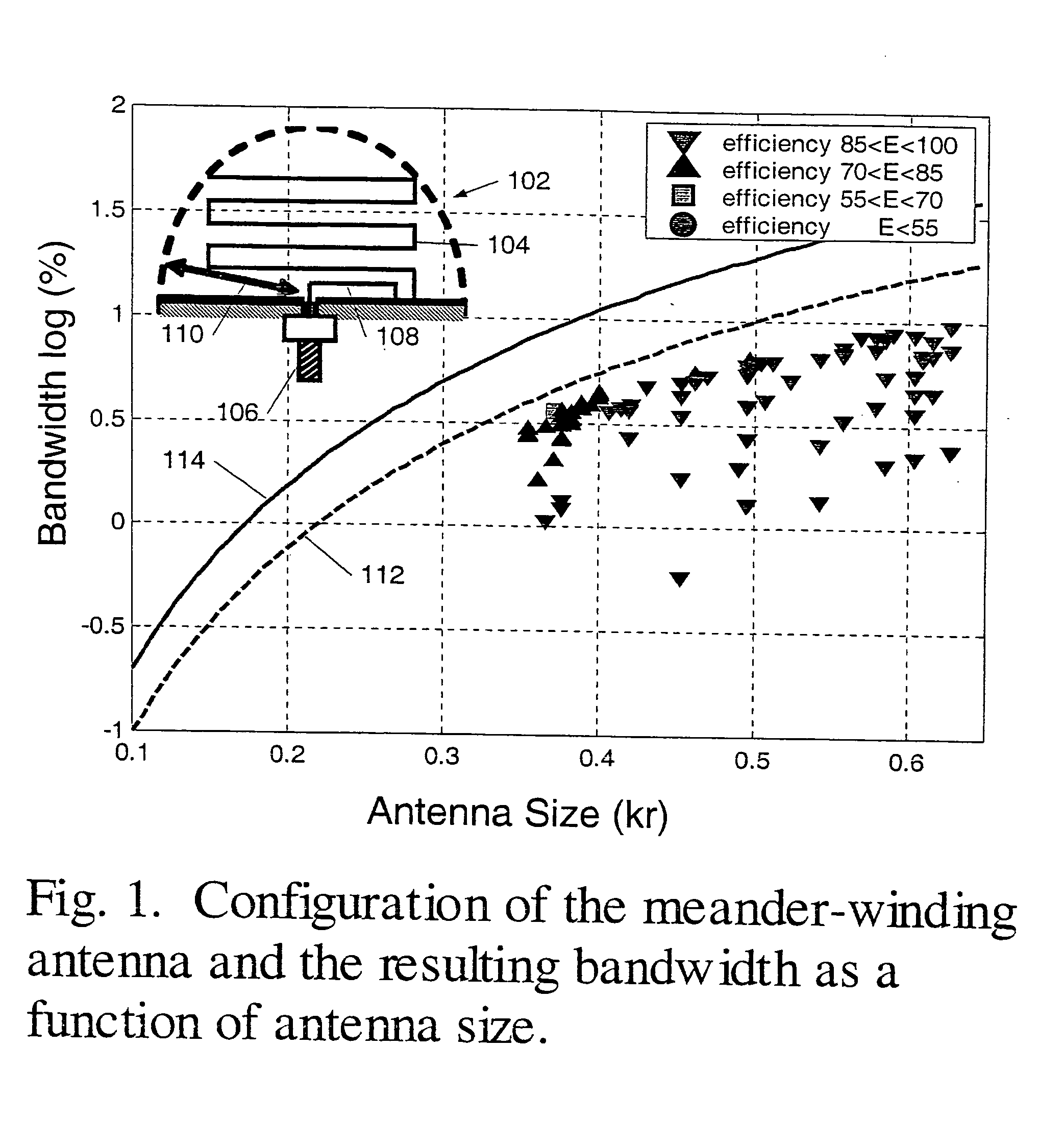
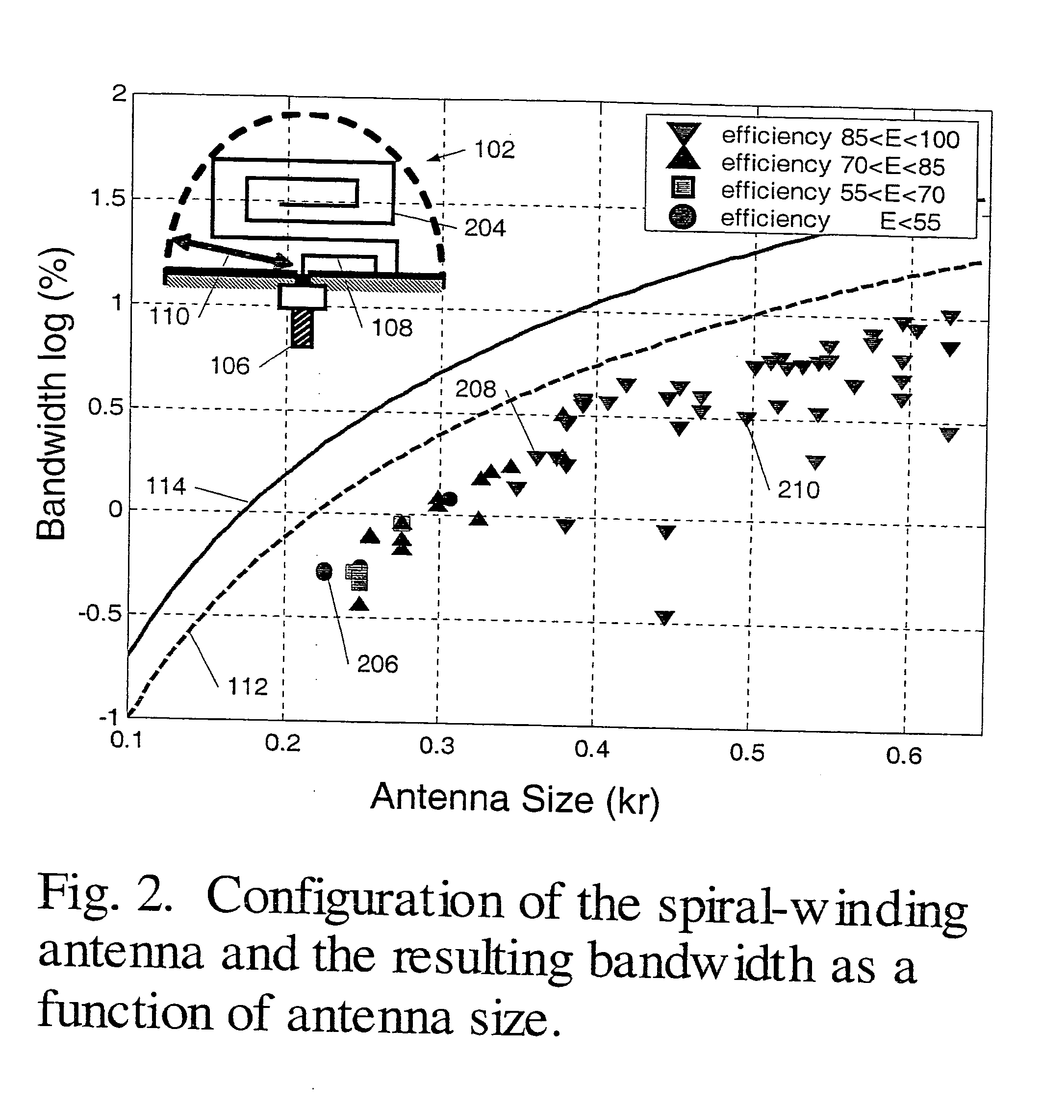
Inductively coupled antennas and methods of designing the same are disclosed. Electrically small antennas having relatively high efficiency and relatively broad bandwidth may be formed by inductively coupling an antenna loop to at least one antenna winding. Such antennas may be substantially planar. Various operating characteristics of such antennas may be adjustable by and / or dependent upon the strength of the inductive coupling between an antenna winding and an antenna loop.

Description

BACKGROUND OF THE INVENTION 1. Field of Invention Embodiments disclosed herein generally relate to methods of designing antennas and antennas designed by those methods. In particular, embodiments relate to antennas with inductively coupled feed. 2. Description of Related Art Electrically small antennas may include antennas with a size about 10% of the operating wavelength of the antenna or less (e.g., 5% of the operating wavelength). Existing designs for electrically small antennas typically have complicated structures. For example, Goubau (reference 6), Dobbins et al. (reference 7) and Foltz et al. (reference 8) each disclose relatively complex antenna designs. Complicated structures may make antenna fabrication difficult. Complicated structures may also be difficult to redesign to meet different operating frequencies. A concern with many electrically small antennas is that the input resistance of such antennas may be relatively small. The small input resistance may cause diffi...

Claims


Application Information

Patent Timeline
Patent Type & Authority Applications(United States)
IPC IPC(8): H01Q1/36H01Q9/42H01Q21/00
CPCH01Q1/36H01Q9/42
Inventor CHOO, HOSUNGLING, HAO
Owner INTELLECTUAL VENTURES HLDG 40
Learn More