Photovoltaic attachment system

a photovoltaic and mounting system technology, applied in the direction of heat collector mounting/support, machine support, light and heating apparatus, etc., can solve the problems of leakage of roof water, additional obstacles for the mounting of photovoltaic panels on top of the roof water, and weakening of the roof structur

Inactive Publication Date: 2005-03-10
HSIAO CHUNG HOU TONY
View PDF30 Cites 14 Cited by
  • Summary
  • Abstract
  • Description
  • Claims
  • Application Information

AI Technical Summary

Benefits of technology

[0004] The present invention is a photovoltaic attachment system for mounting photovoltaic panels on top of a building's roof. The attachment system does not require drilling of holes into the roof and does not affect the integrity of the roof. The photovoltaic attachment system comprises of a grid of photovoltaic panels mounted on top of beams that are attached to the walls around the roof. No holes are drilled into or through the roof. The roof structure is not affected and no leakage of water through the roof will result from the mounting of the photovoltaic panels.

Problems solved by technology

This conventional mounting method often results in leaks in the roof of a building due to improper sealing of the holes through the roof.
Furthermore, the conventional mounting method also weakens the roof structure due to the numerous holes that are drilled through the roof to attach the photovoltaic panels to the roof.
If there are air conditioning and ventilations pipes and ducts on top of the roof, they create additional obstacles for the mounting of the photovoltaic panels on top of the roof using conventional mounting methods.

Method used


Image

  • Photovoltaic attachment system
  • Photovoltaic attachment system
  • Photovoltaic attachment system

Examples


Embodiment Construction

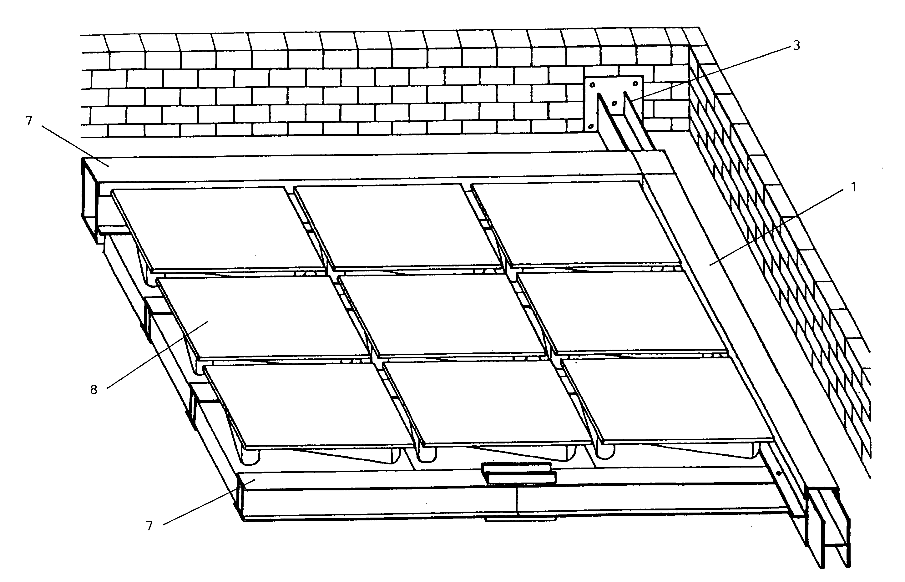
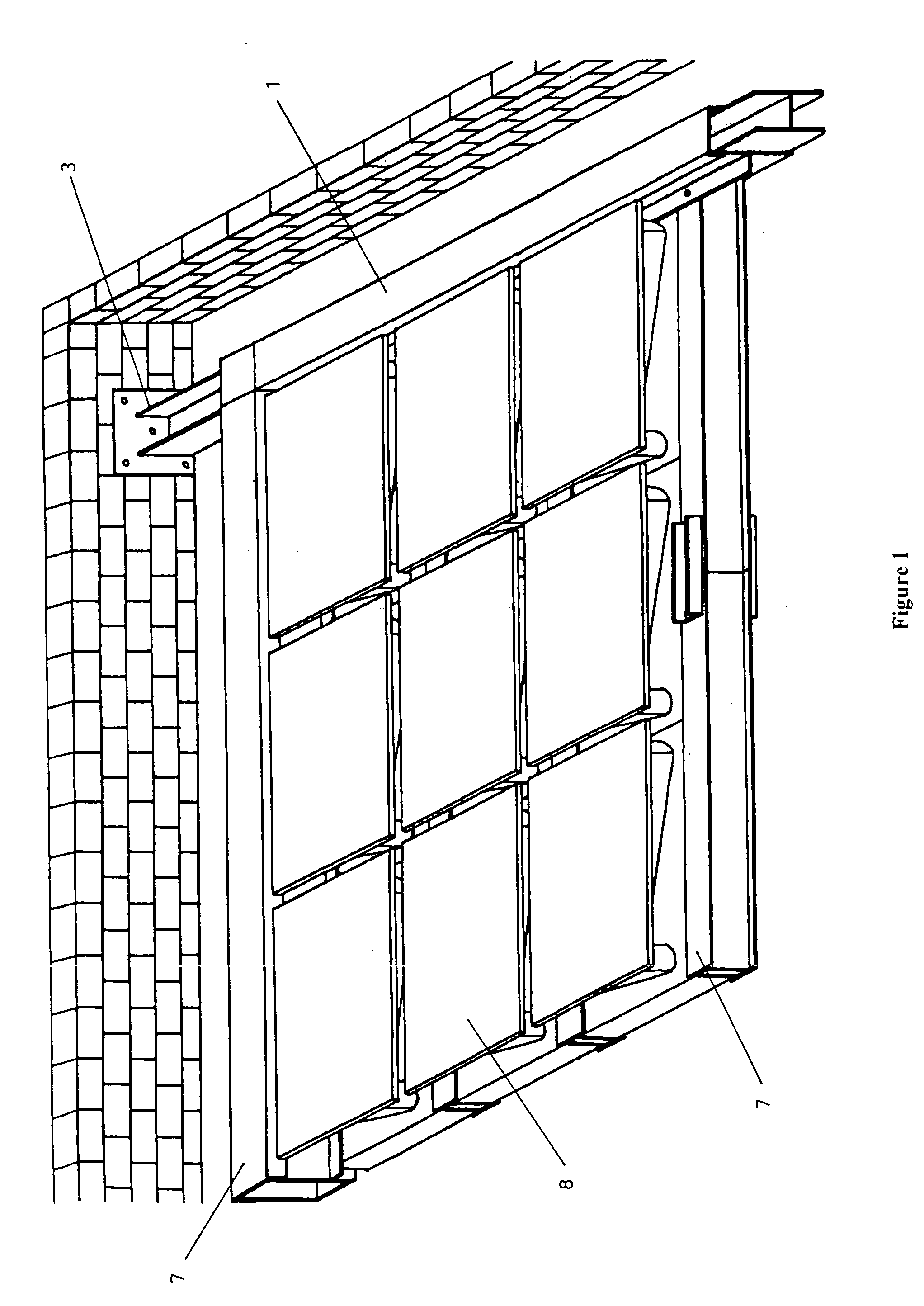
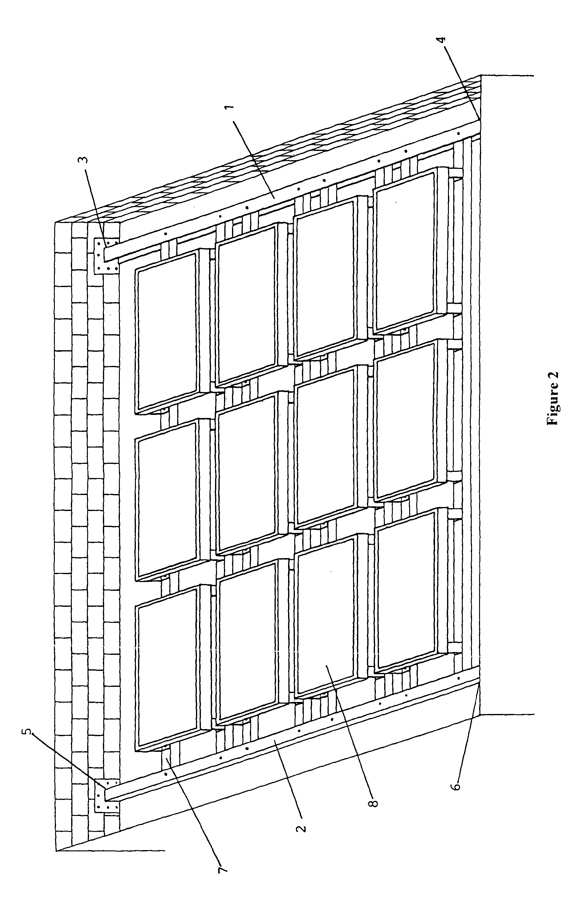
[0016] The current preferred embodiment of the photovoltaic attachment system is shown in FIG. 1. In the preferred embodiment, the photovoltaic attachment system comprises of two beams 1, 2 that are positioned parallel to each other and attached at its ends 3, 4, 5, 6 to two opposite walls on top of a roof. Cross-beams 7 are positioned across and affixed to the two beams 1, 2 to form a grid in which photovoltaic panels 8 are attached. As shown in FIG. 2, the two parallel beams 1, 2 may be oriented parallel to the roof. The two parallel beams 9, 10 may also be oriented at a slope relative to the roof from one end to the other as shown in FIG. 3. This attachment system does not require any penetration of the roof and does not affect the structural integrity of the roof.

[0017] Another embodiment of the photovoltaic attachment system is shown in FIG. 4. In this embodiment, a pair of beams 11, 12 is positioned parallel to each other. One beam 11 is attached along its length parallel to ...


PUM


Abstract

A photovoltaic attachment system for mounting photovoltaic panels on top of a building's roof is disclosed. The attachment system does not require drilling of holes into the roof and does not affect the integrity of the roof. The photovoltaic attachment system comprises of a grid of photovoltaic panels mounted on top of beams that are attached to the walls around the roof. The roof structure is not affected. No holes are drilled into or through the roof and no leakage of water through the roof will result from the mounting of the photovoltaic panels.

Description

BACKGROUND—FIELD OF INVENTION [0001] The present invention relates generally to a photovoltaic mounting system. More specifically, the present invention is a mounting means for attaching photovoltaic panels on top of a building's roof. BACKGROUND—DESCRIPTION OF RELATED ART [0002] The collection of solar energy takes many forms. The most desirable configuration is the direct conversation of solar energy to electricity. The heart of the photovoltaic system is a thin flat layer of semiconductor material. When the material is struck by sunlight, electrons are freed, producing an electric current. The direct-current (DC) power is passed through a DC load, into a storage battery, or converted to alternating current (AC) for general use in electric utility grid. Typically, individual solar cells are ganged together to form photovoltaic modules. Typically, about half the cost of a solar system lies with the solar cell modules, and the remainder is directed toward power conditioning, electri...

Claims


Application Information

Patent Timeline
Patent Type & Authority Applications(United States)
IPC IPC(8): E06B3/00
CPCF24J2/5205F24J2/5243F24J2002/5292H02S20/23Y02B10/20Y02E10/47Y02B10/12F24S25/33F24S25/60F24S2025/02Y02B10/10Y02E10/50
Inventor YEN, KUO-YOWHSIAO, CHUNG-HOU TONY
Owner HSIAO CHUNG HOU TONY
Why Eureka
Try Eureka