
Method of resecting a femoral head for implantation of a femoral neck fixation prosthesis

a femoral neck and fixation technology, applied in the field of hip prostheses, can solve the problems of proximal bone loss, requiring the resection of the majority of the femoral neck, and subsequent curtailment of patient activity, so as to reduce the amount of the femur, reduce the amount of bone loss, and the effect of less invasiv

Inactive Publication Date: 2005-03-03
HOWMEDICA OSTEONICS CORP
View PDF65 Cites 15 Cited by
  • Summary
  • Abstract
  • Description
  • Claims
  • Application Information

AI Technical Summary

Benefits of technology

[0017] It is another object of the present invention to provide an improved and less-invasive prosthesis and implantation method that replaces the femoral head while retaining a substantially intact femoral neck.
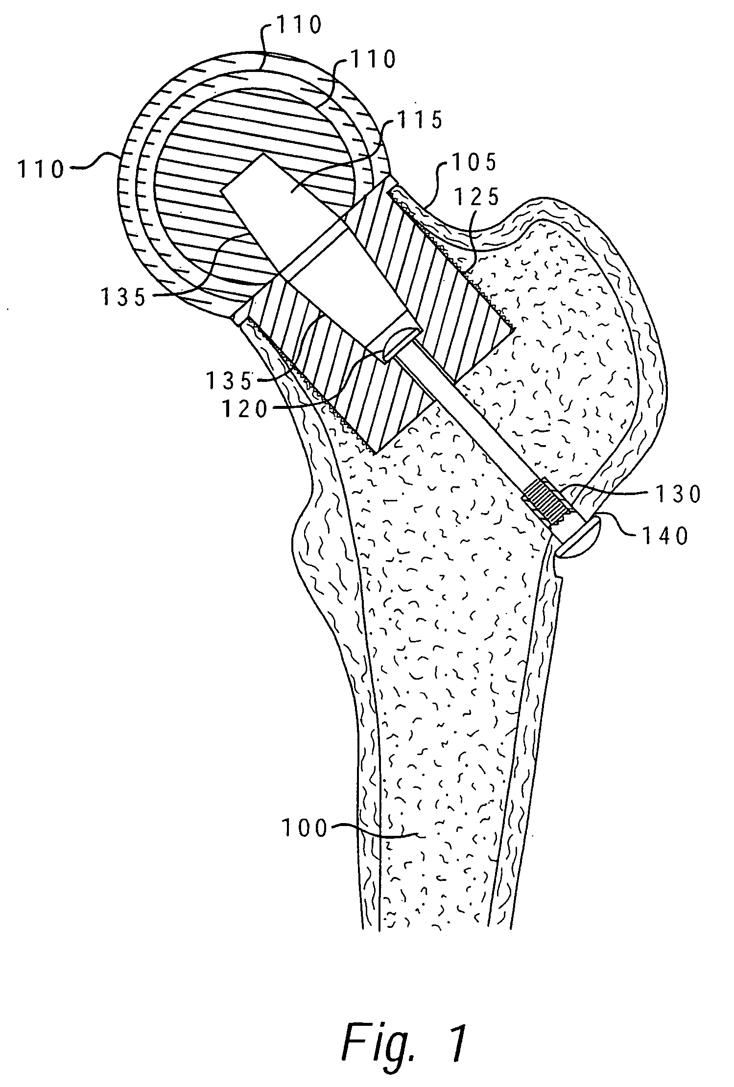
[0018] The foregoing objects are achieved as is now described. A femoral neck fixation prosthesis and method of implanting the prosthesis according to the principles of the present invention, reduce bone loss and avoid the other shortcomings of the prior art by allowing the fixation of a stable femoral head replacement while reducing the amount of the femur that must be removed and reamed for the insertion of the prosthesis. The preferred embodiment provides that the femoral head is attached to a fixation prosthesis, which extends coaxially through the central canal of the femoral neck, into the femur, and is then attached to the opposite lateral wall of the femur. In this manner, the prosthesis serves to imitate the original structure of the femoral neck. No other support members, either crosspins or arms extending into the length of the femur, are required.

Problems solved by technology

This design has the tendency to place unnatural stresses on the femur, which lead to pain and the consequent curtailment of activity for the patient.
Further, present techniques can lead to proximal bone loss and call for the resection of the majority of the femoral neck.
Previously known prostheses for replacing a femoral head that do not extend into the medullary canal have been mechanically complex or have proven troublesome in actual use.
The additional holes and the stresses at the site of fixation are believed to cause trauma to the bone.
The shear forces can be harmful to the greater trochanter and can permit micro-movement of the prosthesis on the unsecured side.
This method is considered invasive because of the need to dislocate the hip and cut through muscle surrounding the hip joint.
Invasive procedures increase the trauma to the patient, the potential for complications, recovery time and the cost.
There are several other significant problems and issues relating to hip arthroplasty.
One problem is encountered with the young, active patient.
Younger patients are more likely to have failure of their primary arthroplasty both due to increased demand on the mechanical construct, and from a pure life expectancy standpoint.
It follows that they are more likely to require a revision and a second revision, which may lead to a catastrophic bone loss situation.
Another problem relates to instability of the hip following implantation of the prosthesis.
This problem still occurs at the same rate that it did 50 years ago.
Still another problem is related to bone loss in patients receiving hip prostheses.
Leg length inequality is another problem associated with hip arthroplasty.
Finally, another problem associated with hip arthroplasty is surgical morbidity.
The surgery usually involves significant blood loss, body fluid alterations, and pain.
Shortly, the surgery is a big operation that hurts.

Method used


Image

  • Method of resecting a femoral head for implantation of a femoral neck fixation prosthesis
  • Method of resecting a femoral head for implantation of a femoral neck fixation prosthesis
  • Method of resecting a femoral head for implantation of a femoral neck fixation prosthesis

Examples


Embodiment Construction

[0050] In the following detailed description of the preferred embodiments, reference is made to the accompanying drawings, which form a part hereof and in which is shown by way of illustration specific preferred embodiments in which the invention may be practiced. These embodiments are described in sufficient detail to enable those skilled in the art to practice the invention, and it is understood that other embodiments may be utilized and that logical mechanical, structural, and chemical changes may be made without departing from the spirit or scope of the invention. To avoid detail not necessary to enable those skilled in the art to practice the invention, the description may omit certain information known to those skilled in the art. The following detailed description is, therefore, not to be taken in a limiting sense, and the scope of the present invention is defined only by the appended claims.

[0051] The present invention provides a femoral neck fixation prosthesis and a metho...


PUM


Abstract

A femoral neck fixation prosthesis and method of using same which reduces bone loss and the avoids the other shortcomings of the prior art by allowing the fixation of a stable femoral head replacement while reducing the amount of the femur which must be reamed for the insertion of the prosthesis. The preferred embodiment provides that the femoral head is attached to a fixation prosthesis, which extends coaxially through the canal of the femoral neck, into the femur, and is then attached to the opposite lateral wall of the femur. In this manner, the prosthesis serves to imitate the original structure of the femoral neck. No other support members, either crosspins or arms extending into the length of the femur, are required.

Description

CROSS-REFERENCE TO RELATED APPLICATIONS [0001] This application is a continuation-in-part of and claims priority to U.S. patent application Ser. No. 10 / 779,353, filed Feb. 14, 2004, which is a continuation of U.S. patent application Ser. No. 10 / 228,907, filed Aug. 27, 2002, now U.S. Pat. No. 6,695,883, which claims priority to U.S. Provisional Application No. 60 / 371,837, filed Apr. 11, 2002. Priority is claimed to all of the above-mentioned applications and patents, and each application and patent is hereby incorporated by reference.BACKGROUND OF THE INVENTION [0002] 1. Field of the Invention [0003] The present application relates generally to hip prostheses and more specifically to an improved method of implanting a femoral neck fixation prosthesis in the femoral neck. [0004] 2. Description of Related Art [0005] A widely used design for replacement of the proximal portion of a femur employs an elongate, often curved, shaft that extends into the medullary canal of the femur. This de...

Claims


Application Information

Patent Timeline
Patent Type & Authority Applications(United States)
IPC IPC(8): A61B17/17A61B17/74A61B17/86A61F2/00A61F2/30A61F2/36A61F2/46
CPCA61B17/175A61F2310/00029A61B17/742A61B17/8665A61B17/8695A61F2/30767A61F2/3601A61F2/4607A61F2/4657A61F2002/30113A61F2002/30156A61F2002/30224A61F2002/30329A61F2002/30332A61F2002/30341A61F2002/30434A61F2002/30438A61F2002/30443A61F2002/30535A61F2002/3055A61F2002/30604A61F2002/30616A61F2002/30774A61F2002/3079A61F2002/30794A61F2002/30797A61F2002/30827A61F2002/30968A61F2002/3611A61F2002/3631A61F2002/365A61F2002/4631A61F2002/4636A61F2002/4658A61F2220/0025A61F2220/0033A61F2220/0041A61F2230/0006A61F2230/0023A61F2230/0069A61F2250/0058A61F2310/00023A61B17/74A61F2002/30339A61F2002/30433A61F2002/4635
Inventor CROFFORD, THEODORE W.
Owner HOWMEDICA OSTEONICS CORP
Learn More