Bearing supporting structure

a bearing and supporting structure technology, applied in the direction of shaft and bearings, rotary bearings, cooling/ventilation/heating modification, etc., can solve the problems of high manufacturing cost, complicated procedures, and a lot of time required to repair, maintain, replace, and mount and dismount bearings quickly and easily. , to achieve the effect of stably positioning, quick mounting and dismounting of bearings

Inactive Publication Date: 2005-03-03
ASIA VITAL COMPONENTS SHENZHEN CO LTD
View PDF7 Cites 0 Cited by
  • Summary
  • Abstract
  • Description
  • Claims
  • Application Information

AI Technical Summary

Benefits of technology

The present invention provides a bearing supporting structure that allows a bearing to stably position in a bearing sleeve on a motor stator unit. The structure also allows for quick mounting and dismounting of the bearing. This is achieved by using a bearing sleeve with a stopper and a segment with an elastic flange that helps position the bearing and a coil around it. The bearing can be easily removed from the sleeve without moving the coil.

Problems solved by technology

The above-mentioned conventional bearing supporting structure therefore has complicate manufacturing process and high manufacturing cost.
Thus, with the conventional bearing sleeve 411, complicate procedures and a lot of time is required to repair, maintain, and replace the bearing 42.

Method used


Image

  • Bearing supporting structure
  • Bearing supporting structure
  • Bearing supporting structure

Examples


first embodiment

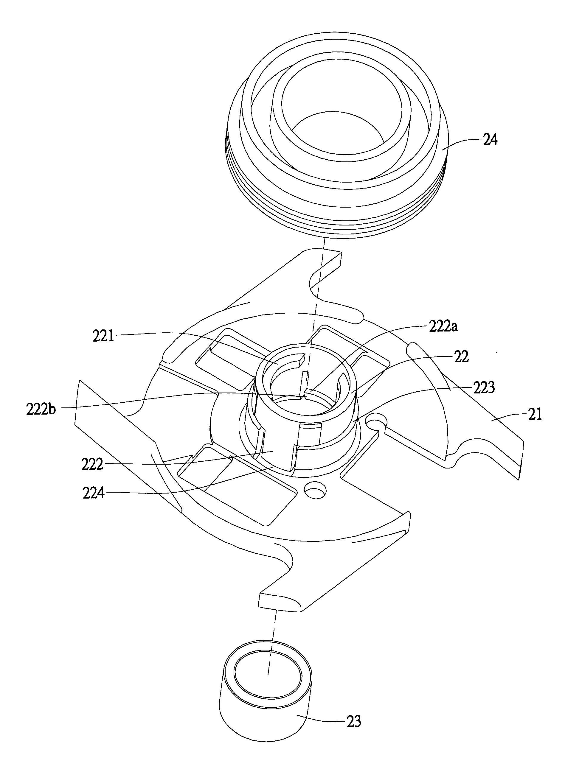
[0026] Please refer to FIGS. 8 and 9 that are front and rear exploded perspective views, respectively, of a bearing supporting structure according to the present invention. As shown, the bearing supporting structure mainly includes a bearing sleeve 22 provided a motor stator unit 21 for supporting a bearing 23 therein. The bearing sleeve 22 is provided on an inner wall surface near an outer end thereof with radially inward projected stoppers 221. An inner end of the bearing sleeve 22 is split to provide a plurality of segments 222. In the illustrated drawings, two segments 222 are shown. Each of the segments 222 is provided on an inner wall surface near an inner end thereof with a radially inward projected flange 222a, an inner side of which is formed into a downward and radially outward inclined surface 222b, enabling a bearing 23 to easily move through the inclined surfaces 222b into the bearing sleeve 22. The stoppers 221 and the flanges 222a are so located that a vertical space ...

second embodiment

[0029] FIGS. 14 to 16 illustrates the present invention. The second embodiment is generally structurally similar to the first embodiment, except that a bearing unit 33 including bearings 331, 333 and bearing spacer 332 is mounted in the bearing sleeve 22. To mount the bearing unit 33 in the bearing sleeve 22, the bearing 331, the bearing spacer 332, and the bearing 333 are sequentially moved into the bearing sleeve 22. Again, the stoppers 221 and the flanges 222a together define between them a vertical space equal to a height of the bearing unit 33, that is, an over all height of the bearing 331, the bearing spacer 332, and the bearing 333, so that the bearing unit 33 may be stably positioned in the bearing sleeve 22 between the stoppers 221 and the flanges 222a.

[0030] In the second embodiment, more than one bearing unit 33 may be mounted in the bearing sleeve 22 depending on actual needs in use. However, the bearing and the bearing spacer are always alternately included in each be...


PUM


Abstract

A bearing supporting structure includes a bearing sleeve provided on a motor stator unit for supporting a bearing therein and a coil therearound. The bearing sleeve is provided on an inner wall surface near an outer end thereof with radially inward projected stoppers, and split at an inner end to provide a plurality of spaced segments having a certain elasticity, each of which is provided at a lower inner surface with a radially inward projected flange having an inclined side surface. The bearing is moved through the flanges into the bearing sleeve to stably position therein between the stoppers and the flanges, so that the bearing may be quickly and easily removed from the bearing sleeve via the elastic segments without the need of moving the coil externally mounted around the bearing sleeve.

Description

FIELD OF THE INVENTION [0001] The present invention relates to a bearing supporting structure, and more particularly to a bearing sleeve that is provided on a motor stator unit, and formed near an outer end with radially inward projected stoppers and at an inner end with spaced elastic segments, which are formed at an inner end with radially inward projected flanges having an inclined side surface, so that a bearing may be stably positioned in the bearing sleeve between the stoppers and the flanges, and easily removed therefrom due to the inclined side surfaces of the flanges and the elasticity of the spaced segments. BACKGROUND OF THE INVENTION [0002] A complete cooling fan mainly includes fan rotor, a bearing, and a motor stator unit. The bearing is mounted in a bearing sleeve provided on the motor stator unit, and the fan rotor has a spindle rotatably mounted in the bearing to enable smooth operation of the fan rotor. In the process of assembling the cooling fan, it is always an ...

Claims


Application Information

Patent Timeline
Patent Type & Authority Applications(United States)
IPC IPC(8): F16C35/02H05K7/20
CPCH05K7/20172F16C35/02
Inventor CHOU, CHU-HSIEN
Owner ASIA VITAL COMPONENTS SHENZHEN CO LTD
Why Eureka
Try Eureka