Shock absorbent end cap for trays

a technology of shock absorption and end caps, which is applied in the direction of paper/cardboard containers, packaging goods types, plastic containers, etc., can solve the problems of reducing the storage space of trays and components, and affecting the process of handling and transportation

Inactive Publication Date: 2005-03-03
PEAK PLASTIC & METAL PRODS INT
View PDF6 Cites 15 Cited by
  • Summary
  • Abstract
  • Description
  • Claims
  • Application Information

AI Technical Summary

Benefits of technology

[0005] It is an advantage of the present invention that it allows smaller sized boxes to be used in the transport and storage of stacks of trays.
[0006] It is a further advantage of the present invention in that shock absorbing packaging material is not generally required to assure protection during handling and transportation of stacks of trays.
[0007] The above advantages, among others, can be achieved singly or in combination.
[0008] In one embodiment of the present invention, an end cap is provided in the form of a box with an open top, having a substantially rectangular base and four substantially rectangular sides, each attached to one of four corresponding edges of the base. The end cap open top has interior length and width dimensions providing clearance for a corresponding width and height respectively of a stack of trays. A depth of the inside of the end cap allows insertion of an end portion of the stack of trays. The end cap is constructed from a shock, absorbent material of thickness and material properties designed to absorb shock for the purpose of protecting the trays and components in the trays. Shock absorbing end caps are placed over both ends of a stack of trays, and the assembly is placed in a dry-pack bag and sealed, and then placed in a cardboard box for transportation.

Problems solved by technology

The addition of foam or bubble wrap requires larger boxes, which consume more storage space, which is a disadvantage.
On occasion, the stacks are boxed with inadequate shock absorbing material, resulting in damage to the trays and components in the process of handling and transportation.

Method used


Image

  • Shock absorbent end cap for trays
  • Shock absorbent end cap for trays
  • Shock absorbent end cap for trays

Examples


Embodiment Construction

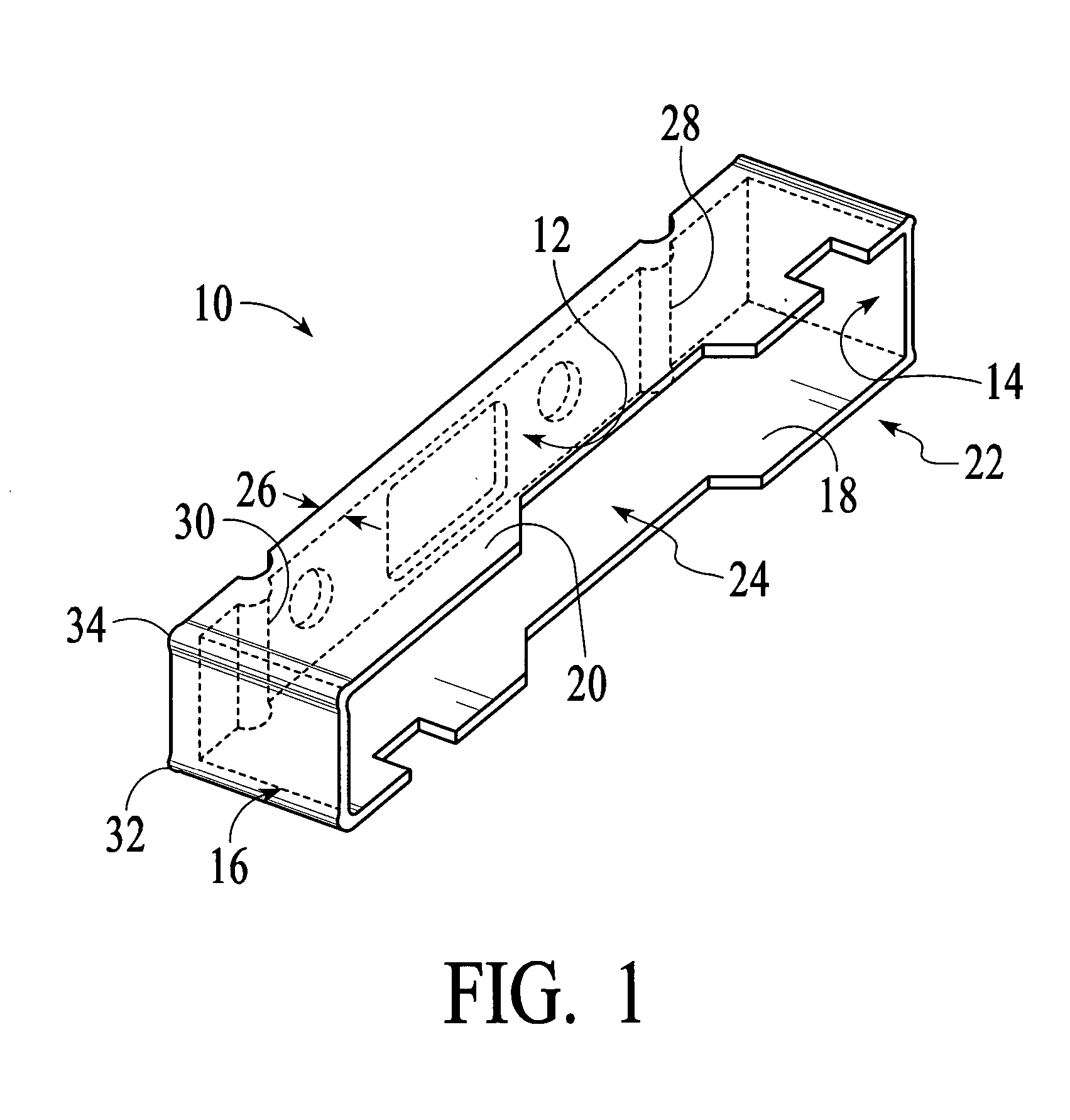
[0014]FIG. 1 shows an end cap 10 according to the present invention, in the form of a box-like structure having a substantially rectangular base 12, and four walls 14, 16, 18 and 20, each extending from an edge of the base to an open end 22. The end cap 10 forms a cavity 24, and is for placement over an end portion of a stack of trays. The end cap 10 is constructed of shock absorbing material, such as rubber or any of various other materials for the purpose of absorbing shock that will be understood by those skilled in the art. The optimum choice of material and thickness such as wall thickness 26 for example, will depend on the combined weight of a tray stack with components. The calculations for determining the optimum material and thickness will be understood by those skilled in the art, and need not be described for any particular sizes and weights in order for the present invention to be understood and implemented. A shock absorbing material by definition in the present disclos...


PUM


Abstract

In one embodiment of the present invention, an end cap is provided in the form of a box with an open top, having a substantially rectangular base and four substantially rectangular sides, each attached to one of four corresponding edges of the base. The end cap open top has interior length and width dimensions providing clearance for a corresponding width and height respectively of a stack of trays. A depth of the inside of the end cap allows insertion of an end portion of the stack of trays. The end cap is constructed from a shock, absorbent material of thickness and material properties designed to absorb shock for the purpose of protecting the trays and components in the trays. Shock absorbing end caps are placed over both ends of a stack of trays, and the assembly is placed in a dry-pack bag and sealed, and then placed in a cardboard box for transportation.

Description

BACKGROUND OF THE INVENTION [0001] 1. Field of the Invention [0002] The present invention relates to methods and apparatus for protecting a stack of trays holding components such as semiconductors, and more particularly to a shock absorbing end cap that fits over end portions of the stack of trays. [0003] 2. Description of the Related Art [0004] Trays for storing and transporting small components such as semiconductors are generally stacked in quantities of two or more trays. The stack is then secured by wrapping it, for example with straps, or / and secured with end caps. For transportation, the stack is placed in a box, surrounded with shock absorbing material such as foam or bubble wrap, etc. The addition of foam or bubble wrap requires larger boxes, which consume more storage space, which is a disadvantage. On occasion, the stacks are boxed with inadequate shock absorbing material, resulting in damage to the trays and components in the process of handling and transportation. SUMMA...

Claims


Application Information

Patent Timeline
IPC IPC(8): B65D81/05B65D81/113B65D85/48B65D85/86
CPCB65D81/053B65D81/058B65D2585/86B65D85/48B65D2581/053B65D81/113B65D2581/055
Inventor WHITE, ROBERT J. JR.
Owner PEAK PLASTIC & METAL PRODS INT
Why Eureka
Try Eureka