
A Conduit Having a Cable Therein

Inactive Publication Date: 2005-03-03
SCHLUMBERGER TECH CORP
View PDF35 Cites 48 Cited by
  • Summary
  • Abstract
  • Description
  • Claims
  • Application Information

AI Technical Summary

Benefits of technology

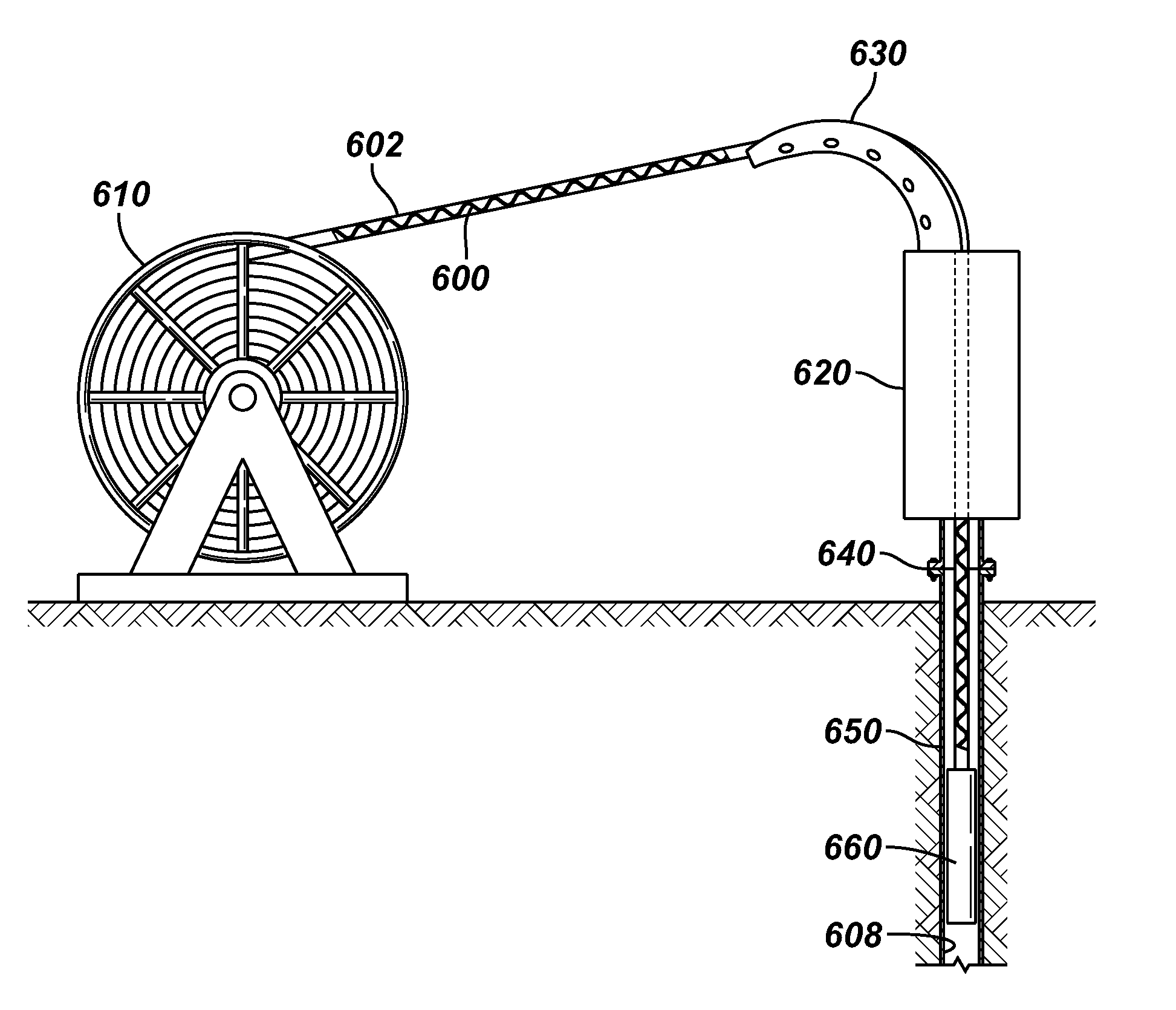
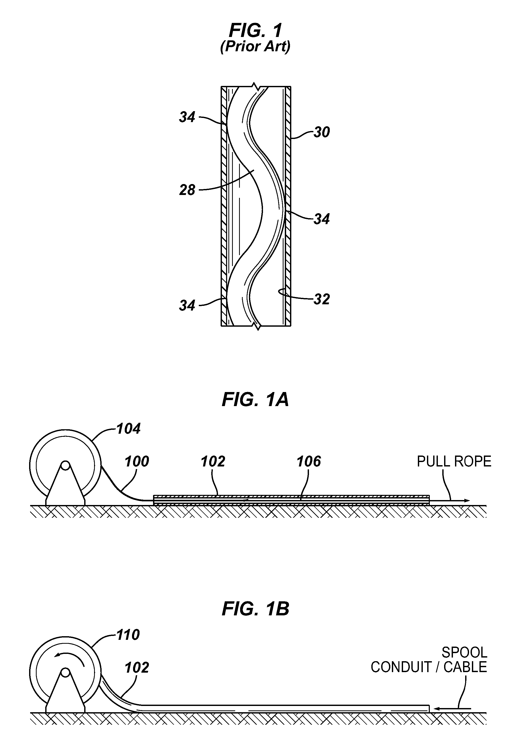
[0008] In general, according to other embodiments of the present invention, a method is provided for putting excess cable into a conduit at surface to enable the cable to uniformly form a helix in the conduit preventing the cable from experiencing tension during deployment into the wellbore.

Problems solved by technology

Since the electric power cable has low tensile strength, the length of power cable that can be freely suspended in inclined tubing is limited.
Such a procedure results in an assembly in which the bottom of the cable is heavily buckled while the upper portion of the cable is in tension.
When additional cable is fed into the conduit, some buckling does occur at the upper end of the conduit, but this buckling may be generally loose.
Therefore, the system described in U.S. Pat. No. 5,954,136 does not produce a uniform buckling along the length of the assembly.
This may cause pull-off of the cable connector or other failure.

Method used


Image

  • A Conduit Having a Cable Therein
  • A Conduit Having a Cable Therein
  • A Conduit Having a Cable Therein

Examples


Embodiment Construction

[0018] In the following description, numerous details are set forth to provide an understanding of the present invention. However, it will be understood by those skilled in the art that the present invention may be practiced without these details and that numerous variations or modifications from the described embodiments may be possible.

[0019] In the specification and appended claims: the terms “connect”, “connection”, “connected”, “in connection with”, and “connecting” are used to mean “in direct connection with” or “in connection with via another element” and the term “set” is used to mean “one element” or “more than one element”. As used herein, the terms “up” and “down”, “upper” and “lower”, “upwardly” and downwardly”, “upstream” and “downstream”“above” and “below” and other like terms indicating relative positions above or below a given point or element are used in this description to more clearly describe some embodiments of the invention. However, when applied to equipment ...


PUM


Abstract

A method of suspending an electric submergible pumping system within a wellbore includes inserting an electric cable within a conduit, such as coiled tubing, before the conduit is deployed downhole. The electric cable is inserted into the conduit at the surface and is permitted to buckle in a manner so that the electric cable buckles and uniformly contacts an interior surface of the conduit at a plurality of locations along the entire length of coiled tubing to prevent longitudinal movement of the electric cable within the conduit. An electric submergible pumping system is then connected to the conduit, and the electric cable is connected to an electric motor of the electric submergible pumping system. The electric submergible pumping system and the conduit are inserted into the wellbore.

Description

CROSS REFERENCE TO RELATED APPLICATIONS [0001] This application claims the benefit under 35 U.S.C. §119(e) of U.S. Provisional Patent Application Ser. No. 60 / 495,663, entitled “CONDUIT HAVING A CABLE THEREIN,” filed Aug. 15, 2003.BACKGROUND OF INVENTION [0002] The present invention relates generally to the field of cables, and more particularly to a device and method for providing a cable in a conduit. [0003] An electric submergible pump (ESP) may be suspended in a well from coiled tubing with an electric cable to power the pump inside the coiled tubing. Produced fluid is pumped up the casing to coiled tubing annulus. Since the electric power cable has low tensile strength, the length of power cable that can be freely suspended in inclined tubing is limited. Therefore, the cable may be clamped, banded or strapped to the outside of the tubing at intervals, as disclosed in U.S. Pat. No. 4,681,169, which is hereby incorporated herein by reference. Alternatively, the cable may be dispos...

Claims


Application Information

Patent Timeline
IPC IPC(8): E21B17/20H02G1/08
CPCE21B17/206H02G1/086H02G1/08E21B17/20G02B6/44H02G1/085
Inventor BIXENMAN, PATRICK W.FRAKER, MARKRIOUFOL, EMMANUELEBNER, PAULGARRETT, DAVID
Owner SCHLUMBERGER TECH CORP
Learn More