
Apparatus and method for treating synthetic grass turf

a technology of artificial grass and apparatus, applied in the direction of cleaning equipment, applications, cleaning equipment, etc., can solve the problems of reducing the proper resiliency and shock absorption properties required, weeds growing into artificial grass surfaces are unwanted, and require maintenan

Inactive Publication Date: 2005-03-03
FIELDTURF TARKETT
View PDF9 Cites 52 Cited by
  • Summary
  • Abstract
  • Description
  • Claims
  • Application Information

AI Technical Summary

Benefits of technology

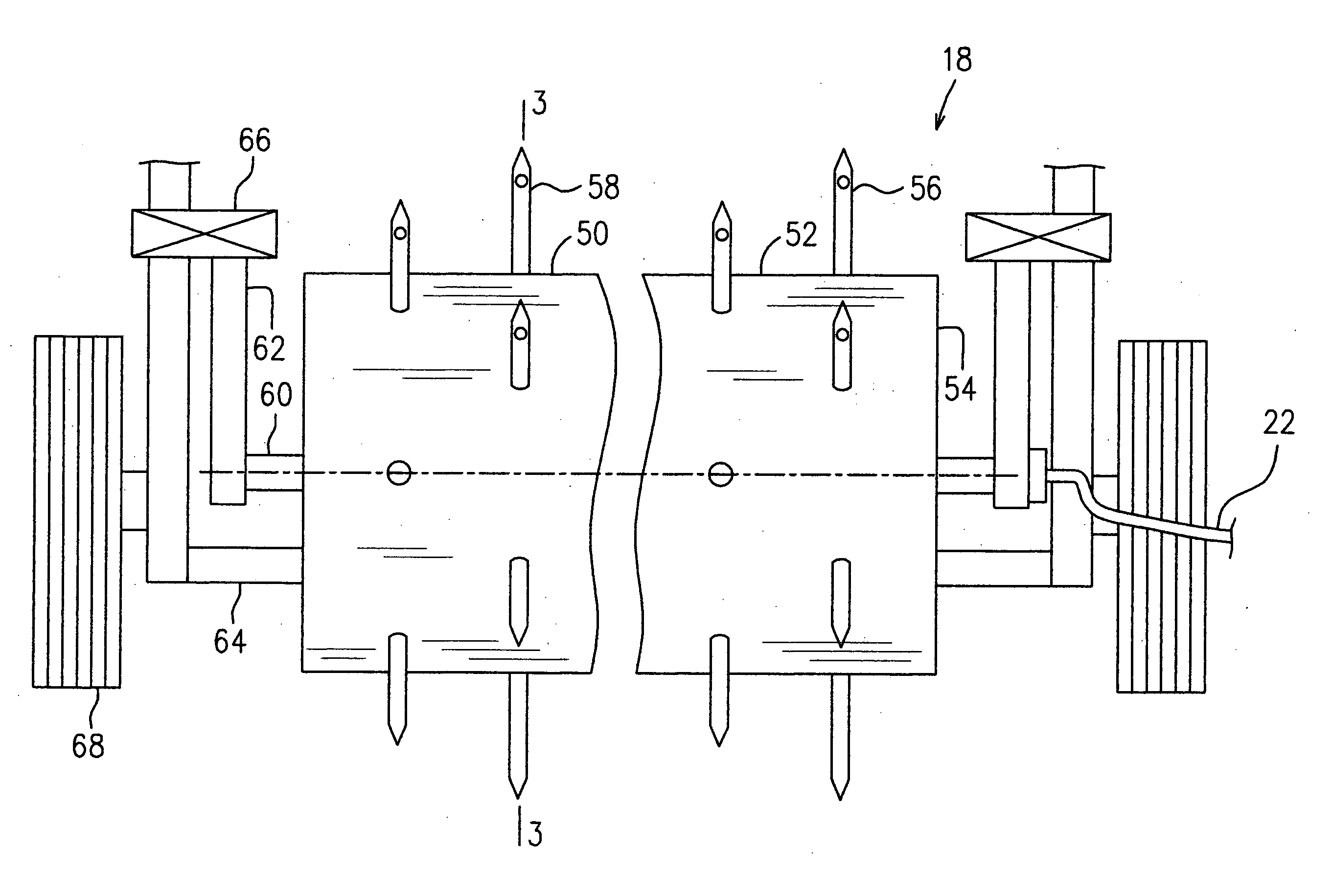
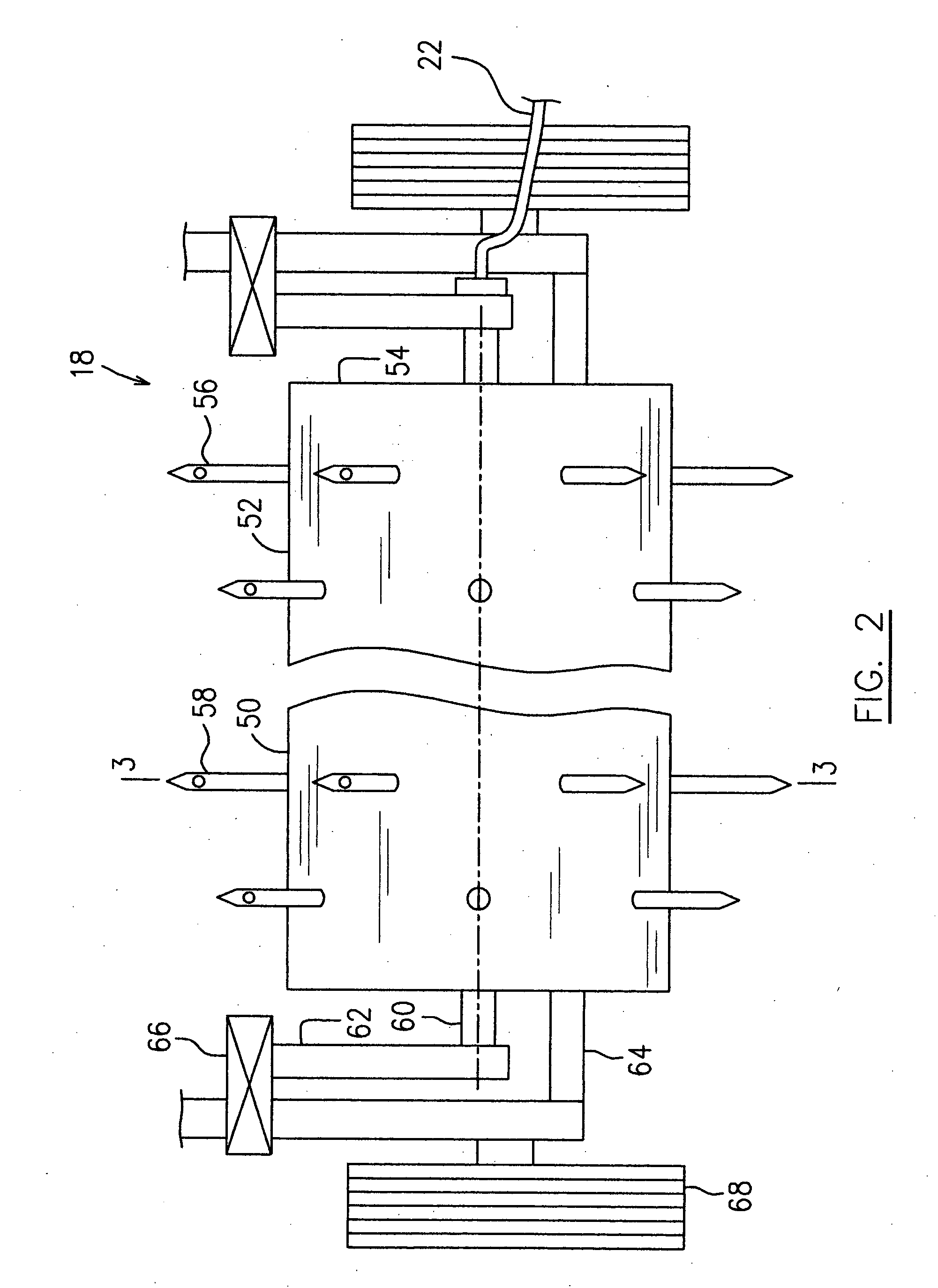
[0011] In accordance with one aspect of the present invention, there is provided an apparatus for treating a synthetic grass turf which comprises a hollow cylinder including a plurality of hollow spikes extending radially and outwardly therefrom. Each of the spikes has an orifice therethrough in fluid communication with an inner space defined within the hollow cylinder. The hollow cylinder is rotatably supported on a support frame at a predetermined height with respect to the synthetic grass turf when the support frame is positioned on the synthetic grass turf. The apparatus further includes a pressurized fluid system for controllably supplying pressurized fluid into the hollow cylinder and thereby enabling fluid to be expelled from at least a number of the spikes to treat the synthetic grass turf when the apparatus moves on the synthetic grass turf thereby causing the hollow cylinder to rotate.
[0015] In accordance with another aspect of the present invention, there is provided a method for treating a synthetic grass turf. The method of the present invention comprises a step of directing pressurized fluid such as air or liquid into a depth of the synthetic grass turf for treatment, using a hollow spike roller rolling on the synthetic grass turf. The hollow spike roller enables fluid to be expelled from a number of hollow spikes that penetrate a top surface of the synthetic grass turf to the depth thereof without damaging the fibers.
[0017] In another example of the synthetic grass turf treatment applications, water can be directed to a relatively greater depth of the synthetic grass turf for flushing a drainage system beneath the synthetic grass turf with or without a surfactant type of fluid, for example a spacing grid preferably made of an extruded tri-plannar polypropylene geotextextile material, as is described in the Applicant's Canadian Patent Application 2,393,240 filed on Jul. 12, 2002. It can also be directed to inject a surfactant deep into the fibers at the level of the backing material in order to help flush the fine particles of dust that accumulate over time through the backing.

Problems solved by technology

In most cases, having weeds grow into an artificial grass surface is unwanted and requires maintenance to remove and or prevent such growth.
The compacted layer can substantially reduce correct drainage of the surface and also reduces the proper resiliency and shock absorption properties required for sports, and therefore, may cause injury to the players.
However, high pressure water washing is a messy process and usually necessitates replacement of much of the particulate, and a considerable amount of leveling work.
Furthermore, soft plastic brushes are not very effective in removing infill to a significant depth, hard plastic brushes are too abrasive for the fibers, and wire brushes can damage the synthetic grass fibers.
However, the pressure of the air jets above the synthetic grass required to adequately penetrate the infill can damage these synthetic fibers.
However, this substantially agitates the infill and may mix the various layers of infill in ways that may not be favorable to the originally designed characteristics of the installation.
Projecting air from the top of the synthetic grass does not afford proper controls in order to achieve control of the infill.
These apparatuses and methods therefore, have limited applications and have a reduced performance when used to renovate synthetic grass turfs having relatively thick infill layers, as disclosed in the Applicant's prior art patent.
Increasing the air pressure may improve renovating performance but over-pressurized air jets will cause further damage to the synthetic grass fibers.

Method used


Image

  • Apparatus and method for treating synthetic grass turf
  • Apparatus and method for treating synthetic grass turf
  • Apparatus and method for treating synthetic grass turf

Examples


Embodiment Construction

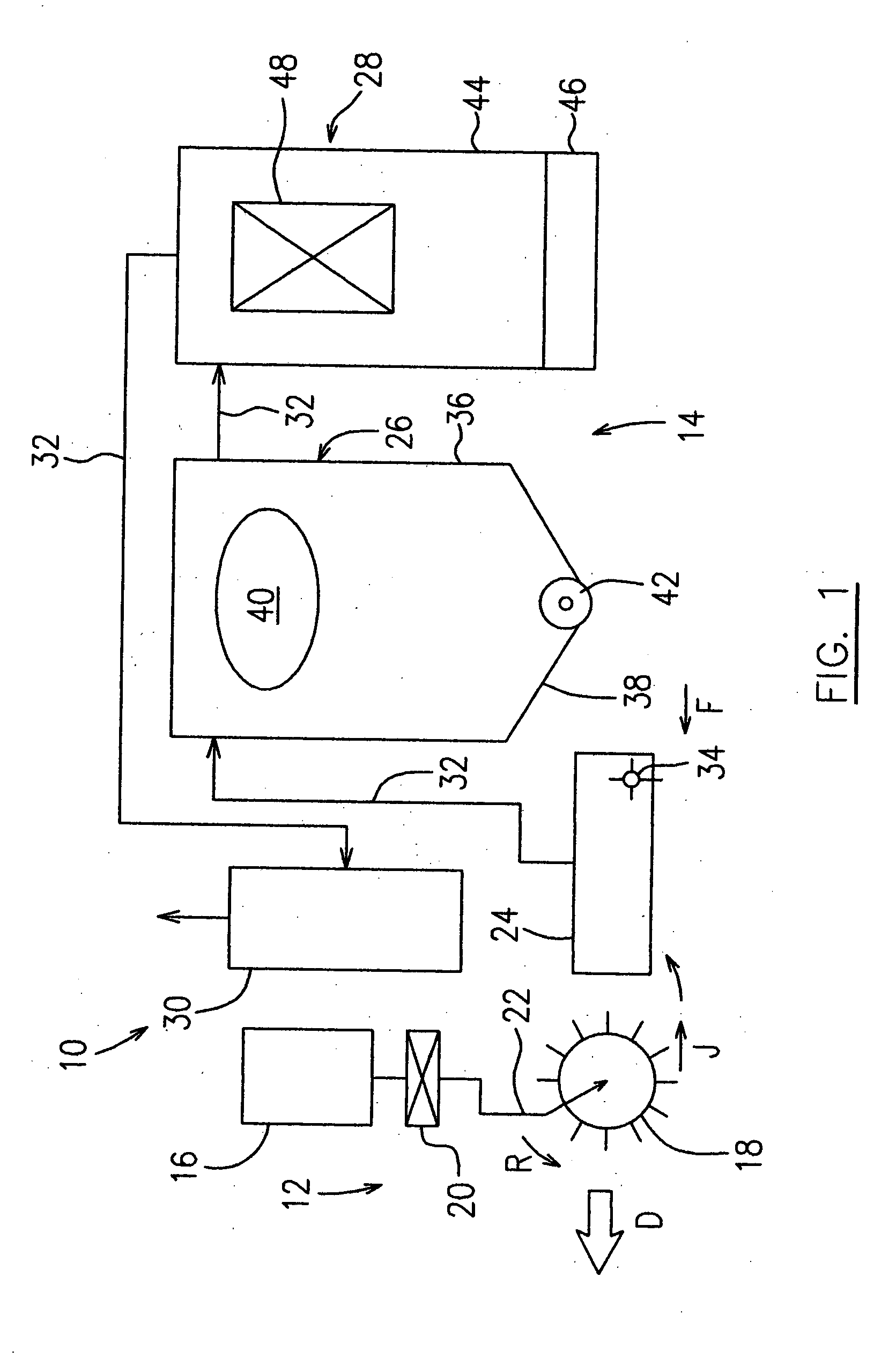
[0028]FIG. 1 is a diagram schematically illustrating a grass turf treatment apparatus which is particularly useful for treating synthetic grass turfs. However, the apparatus can also be used to treat natural grass turfs. According to one preferred embodiment of the present invention, the apparatus which is generally indicated by numeral 10, includes a fluid ejection system 12 and a vacuum system 14.

[0029] The fluid ejection system 12 generally includes a pressurized fluid source 16. In various applications, the pressurized fluid source 16 varies when different types of fluid are required. This embodiment illustrates the use of pressurized air, which is more commonly but not exclusively used in a synthetic grass turf treatment operation, and so the fluid source 16 is preferably an air compressor. The fluid ejection system 12 employs a hollow spike roller assembly 18 to direct the pressurized air in a desired direction to a depth of a synthetic grass turf to be treated. This means th...


PUM


Abstract

An apparatus for renovating and / or cleaning a synthetic grass turf, or for other synthetic grass turf treatments according to the present invention, employs a hollow spike roller which rolls on the synthetic grass turf to enable air jets or other fluids to be expelled from a number of hollow spikes penetrating to a depth of the synthetic grass turf. The penetration depth of the hollow spikes, the angle of air jets and the duration of the individual air jets being expelled, are all adjustable or predetermined, such that the apparatus of the present invention can be conveniently used in various applications for treating synthetic grass turfs. The apparatus reduces or eliminates the potential damage to the grass fibers which presents with use of conventional brushes or highly pressurized fluid jets, and thereby provides efficient performance.

Description

FIELD OF THE INVENTION [0001] The present invention relates to an apparatus and method for treating synthetic grass turf particularly, but not exclusively, used as sports surfaces. Such synthetic grass turf is generally infilled with a layer of sand and / or other particulate material as part of its structural makeup. BACKGROUND OF THE INVENTION [0002] A synthetic grass turf generally comprises a synthetic backing sheet from which extend tufts of simulated grass fibers of a plastic material. The backing sheet is placed on a base substrate having drainage functions. Sand and / or other materials are layered over the backing sheet filling the spaces between the simulated grass fibers so that the simulated grass fibers remain substantially erect, and produce a flat surface which provides a ball-rebound similar to a natural grass court surface. [0003] One typical example of the infill layers is described in the Applicant's U.S. Pat. No. 5,958,527, issued on Sep. 28, 1999. The exemplary infi...

Claims


Application Information

Patent Timeline
IPC IPC(8): A01B45/02A47L5/14A47L9/08E01C23/082E01H1/08E01H1/10
CPCA01B45/02A47L5/14E01H1/103E01C23/0825E01H1/0845A47L9/08
Inventor PREVOST, JEAN
Owner FIELDTURF TARKETT
Learn More