
Pulse abnormality monitor and pulse abnormality warning system

a technology of abnormality detection and monitor, which is applied in the field of pulse abnormality monitor and pulse abnormality warning system, can solve the problem of not being able to monitor pulse abnormalities all the time in daily life, and achieve the effect of automatic detection of pulse abnormalities and high effectiveness

Inactive Publication Date: 2005-02-17
PANASONIC CORP
View PDF2 Cites 24 Cited by
  • Summary
  • Abstract
  • Description
  • Claims
  • Application Information

AI Technical Summary

Benefits of technology

[0006] An objective of the present invention is to provide a device and a system whereby pulse abnormalities can be accurately detected in daily life.
[0007] It is said that the range of normal pulses is varied for each posture of a person. According to human engineering, it is said that normal pulses in an upright position range from 90 to 100 pulses / minute, normal pulses in a seated position range from 60 to 100 pulses / minute, and normal pulses in a lie position range from 40 to 60 pulses / minute. Thus, the posture of a body and a change in activity amount are calculated along with a pulse and it is judged whether or not the pulse is within the normal range in the posture and the activity amount, so that pulse abnormalities can be detected with accuracy. Further, detected information about pulse abnormalities is automatically transmitted to the doctor and family of a patient, so that the pulse abnormalities of the patient can be evaluated remotely. Moreover, mobile phones are set as transmitting terminals, so that the state can be automatically monitored by the doctor and family even during travel.
[0050] According to the present invention, it is possible to automatically detect pulse abnormalities while a person requesting a pulse evaluation lives an ordinary life. Further, pulse abnormalities obtained from the device are automatically transmitted to the doctor of a patient or the like, so that the pulse abnormalities of the patient can be remotely evaluated with high effectiveness.

Problems solved by technology

However, a method of accurately evaluating whether a measured pulse is abnormal or not has not been proposed yet and thus such an evaluation substantially depends upon the decision of an expert such as a doctor under the present circumstances.
Thus, it has been impossible to monitor pulse abnormalities all the time in daily life.

Method used


Image

  • Pulse abnormality monitor and pulse abnormality warning system
  • Pulse abnormality monitor and pulse abnormality warning system
  • Pulse abnormality monitor and pulse abnormality warning system

Examples


embodiment 1

[0092] An abnormal pulse monitor of Embodiment 1 will be discussed below in accordance with the accompanying drawings.

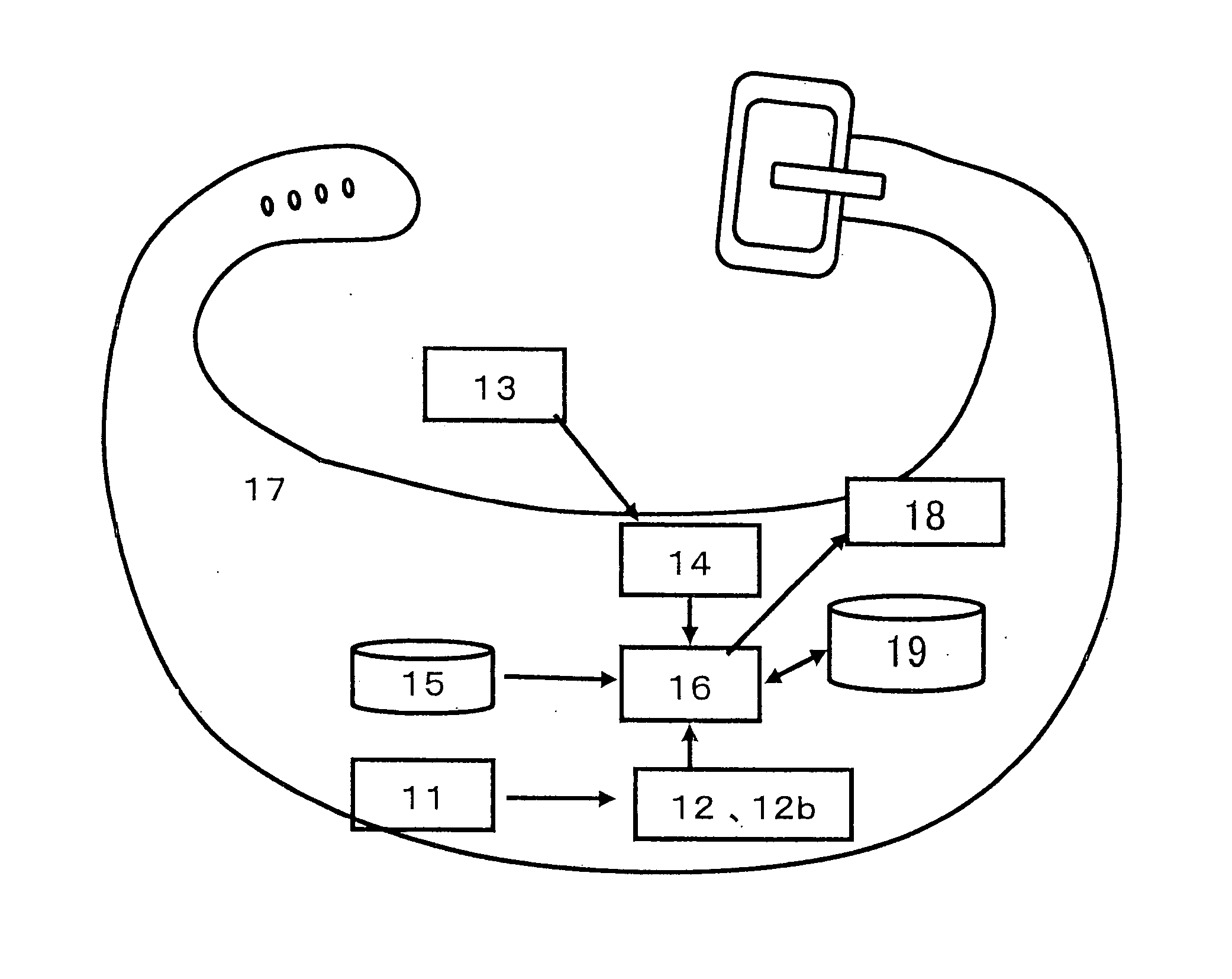
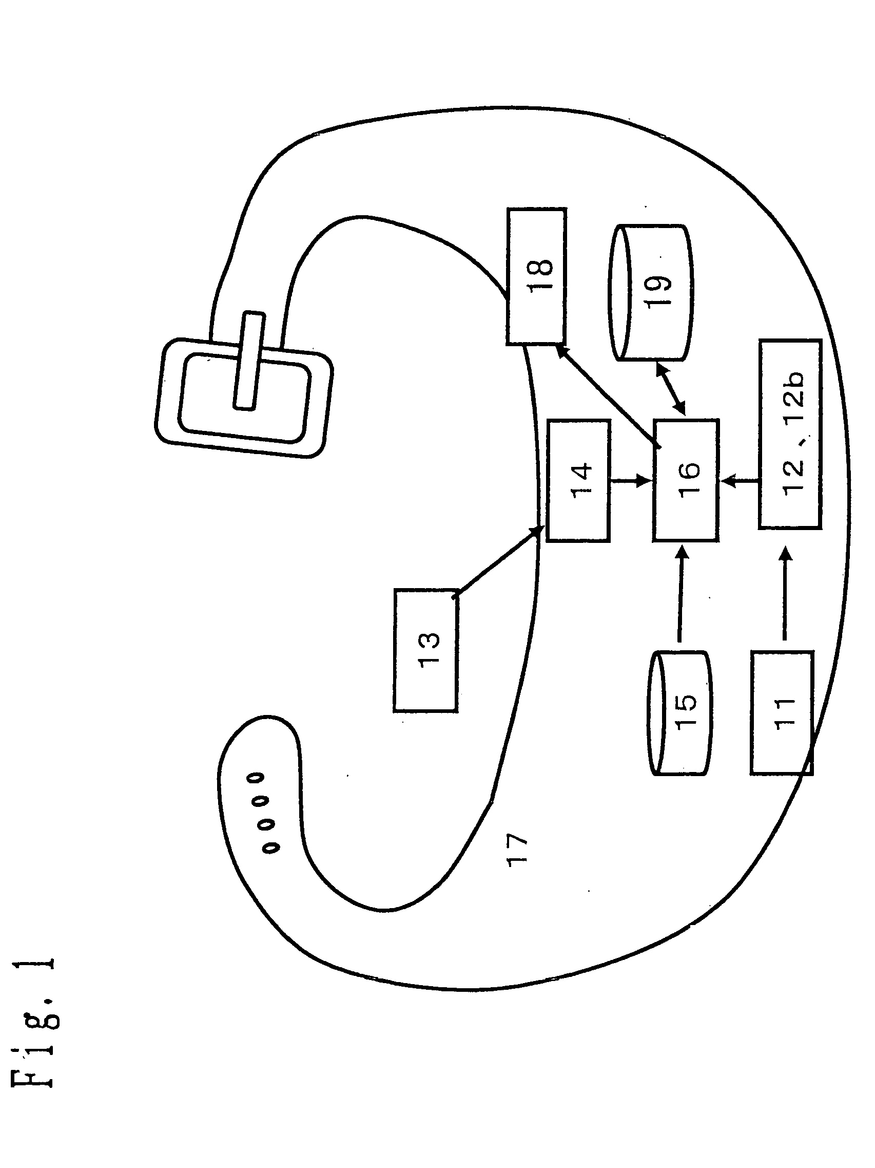
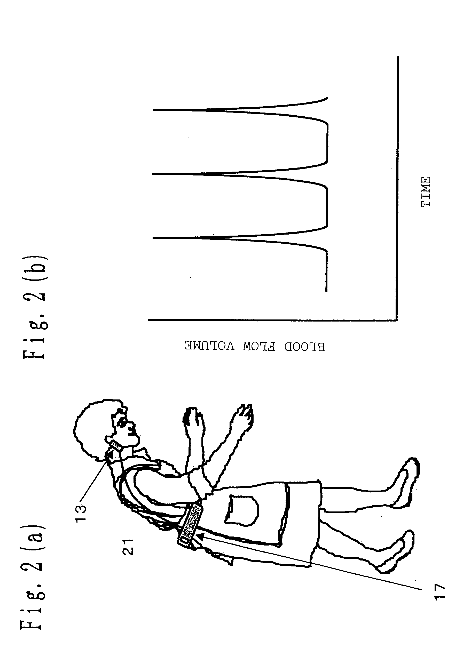
[0093]FIG. 1 is a schematic structural diagram showing the abnormal pulse monitor according to Embodiment 1 of the present invention. The following will describe the configuration of the present embodiment. Embodiment 1 is constituted of an acceleration sensor 11 of detecting a gravitational acceleration, a posture judging section 12 of judging the posture of a body based on a gravitational acceleration obtained by the acceleration sensor 11, a rheometer 13 of measuring a pulse wave, a pulse calculating section 14 of calculating the pulse of a body based on a change in blood flow that is obtained by the rheometer, a memory 15 of storing judgment information for judging an abnormal pulse, and an abnormal pulse judging section 16 of judging the abnormality of a pulse by referring to the memory 15 based on pulse information calculated by the pulse calculating section 1...

embodiment 2

[0125] An abnormal pulse monitor of Embodiment 2 will be discussed below in accordance with the accompanying drawings. FIG. 14 is a schematic structural diagram showing an abnormal pulse alarming system according to Embodiment 2 of the present invention.

[0126] The configuration of Embodiment 2 will be discussed below. Embodiment 2 is constituted of an abnormal pulse monitor 17 configured as FIG. 1, an abnormality transmitting section 121 which is connected to an abnormal pulse judging section 16 in the abnormal pulse monitor 17 and carries out radio communication when a pulse is judged to be abnormal by the abnormal pulse judging section 16, abnormality receiving means 122 of receiving a signal indicating abnormality transmitted from the abnormality transmitting section, and an alarm receiver 123 which is operated when the abnormality receiving means 122 receives an abnormal signal.

[0127] The abnormality receiving means 122 and the abnormal pulse monitor 17 communicate with each o...

embodiment 3

[0129] An abnormal pulse monitor of Embodiment 3 will be discussed in accordance with the accompanying drawings. FIG. 14 is a schematic structural diagram showing an abnormal pulse alarming system according to Embodiment 3 of the present invention. The configuration of Embodiment 3 will be discussed below.

[0130] According to Embodiment 3, a plurality of PHSs 131 are set as the alarm receivers of the system shown in FIG. 14. Unique ID information is added to the devices of users 132 who wear abnormal pulse monitors 17, and an ID is added to state information to be transmitted in communication with abnormality receiving means 122, so that it is decided which of the users 132 transmitted the state information. Based on the decision results, the abnormality receiving means 122 transmits state signals separately to registered information destinations such as the doctor or family of the user 132. On the PHS 131 having received the information, the pulse abnormality of the user 132 can be...


PUM


Abstract

A device of automatically judging pulse abnormalities based on a pulse judgment result and a posture judgment result or an activity amount, including means of measuring a pulse wave of a body, means of calculating a pulse of the body based on the pulse wave measured by the measuring means, means of detecting an acceleration of the body, means of detecting and judging a posture or an activity amount of the body based on the acceleration, and means of judging abnormality based on judgment information predetermined according to the calculated pulse information and the detected and judged posture information or the activity amount.

Description

TECHNICAL FIELD [0001] The present invention relates to a device and a system that detect the state of a body and issue an alarm at a time of abnormal state. BACKGROUND ART [0002] Care for elderly people has recently received attention against the backdrop of the arrival of an aging society. Particularly special emphasis is placedon care for the elderly having a disease such as a chronic illness and thus it is believed that automatic monitoring on the action of the elderly and automatic reporting made to the outside in the event of an abnormal state are considerably significant in terms of care. Further, in consideration of a recently increasing number of small size households or nuclear families, automatic monitoring for detecting an abnormal state of people as well as the elderly is quite effective in terms of the early detection of an abnormal state. Particularly in the case of people having a heart disease, an abnormal state appears as an abnormal pulse including an increased pu...

Claims


Application Information

Patent Timeline
IPC IPC(8): A61B5/00A61B5/024A61B5/0245A61B5/11
CPCA61B5/0002A61B5/024A61B5/02416A61B5/02455A61B5/6823A61B5/1118A61B2562/0219A61B5/6831A61B5/1116
Inventor TANAKA, SHINJIINOUE, SHIGEYUKIYAMAMOTO, HIROSHI
Owner PANASONIC CORP
Learn More