Industrial robot

Inactive Publication Date: 2005-02-17
ABB (SCHWEIZ) AG
View PDF8 Cites 18 Cited by
  • Summary
  • Abstract
  • Description
  • Claims
  • Application Information

AI Technical Summary

Benefits of technology

[0012] The object of the present invention is to reduce the operating time that is lost as service time when replacing a cable harness. The object is thus to arrange an industrial robot that makes possible rapid replacements or supplementations of the whole of or parts of a cable harness and that the cable harness as such is adapted so as to have a comparatively longer service life. The cable harness is preferably arranged so that, during movement of the robot tool, the cable harness manages a bending of more than 90° while being simultaneously rotated.
[0016] The solution according to the invention comprises shortening the time for service shutdowns by making possible simple and rapid cable harness replacements. In an advantageous embodiment, the body according to the invention is arranged axially divided into two separate parts that are coaxially series-connected and detachably connected by, for example, a quick coupler. The first part is secured to the first end of the cable harness. The second part is detachably connected to, for example, a turning disc in a robot wrist. It is to be understood here that the quick coupler withstands the high water and air pressures prevailing.
[0017] In an additional embodiment of the invention, the cable harness is provided at its first end with a body according to the invention and at its second end arranged with a dividing section, wherein the dividing section implies that the cable harness is divisible into two parts in the longitudinal direction. The cable harness is coupled by means of, for example, a quick coupler at the dividing section. This affords the possibility of simply and rapidly detaching and replacing only part of the cable harness. For example, a cable harness part according to the invention constitutes a comparatively shorter internal cable harness, which is drawn through a robot wrist and adapted to be connected to or detached from a turning disc.
[0018] It is part of the inventive concept that a body according to the invention is detachably built into the second robot unit. In a further embodiment, the body according to the invention is radially divided into at least two sub-bodies. The division into sub-bodies facilitates leading the cable harness through the narrower passages in a manipulator, which will be explained in greater detail below. The sub-bodies are then mounted into, for example, a turning disc and are then arranged detachably built in. The sub-bodies hence offer a simple connection of the power supply to a robot tool.
[0020] The solution according to the invention comprises extending the service life of a cable harness by reducing the internal wear in the cable harness and then, in particular, by eliminating the axial changes in length that occur in the wrist portion of a cable harness when bending / rotating a robot tool.

Problems solved by technology

In an industrial robot, therefore, the cable harness is subjected to movements repeated in cycles, and these movements result in wear on individual strands included therein.
For one thing, the individual strand is worn, and, for another, wear arises between the individual strands in the cable harness.
If the wear is allowed to continue for a long time, it leads to damage to the cable harness, which in turn leads to unwanted and, in the worst case, sudden shutdowns.
Therefore, the operating routine comprises replacing a worn-out cable harness with a new cable harness in good time, according to scheduled service intervals, before a risk of damage and shutdown arises.
In the operation of industrial robots, there is a need to minimize the time for service of the robot, since a shut-down for service entails non-productive time and thus increased operating costs.
The axial displacements lead to abrasion between the individual strands and between the strands and the outer casing of the cable harness.
The abrasion results in unwanted wear of the cable harness.

Method used


Image

  • Industrial robot
  • Industrial robot
  • Industrial robot

Examples


Embodiment Construction

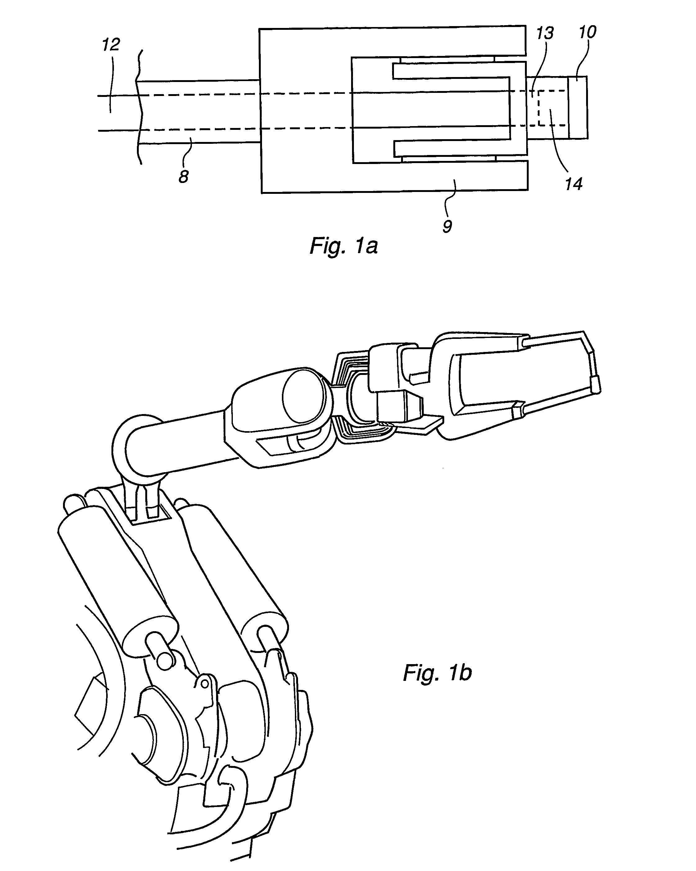
[0039] The invention relates to an industrial robot and the invention is exemplified in FIG. 1 by a six-axis robot 1 comprising a manipulator 2 with a control system (not shown). The manipulator 2 exhibits a robot foot 3, a stand 4, and a robot arm 5. The stand 4 is rotatably arranged on the robot foot 3. The robot arm 5 is rotatably arranged on the strand at a joint 6. The robot arm 5 comprises at least a first arm part 7 supporting a vertically oriented, rotating upper arm 8 as well as a wrist 9, which are rotatably arranged in relation to each other. At its free end, the upper arm 8 supports the wrist 9, which comprises a turning disc 10 provided with a robot tool 11 where the wrist 9 and the turning disc 10 are rotatably and bendably movable in relation to each other.

[0040] A cable harness 12 is drawn by its first end 13 through the upper arm 8, through the wrist 9 and up to the turning disc 10, which is shown in FIG. 1a. At the first end 13 of the cable harness, a body 14 acco...


PUM


Abstract

An industrial robot comprising a manipulator with a control system, where the manipulator comprises a hollow, first robot unit (9) and a second robot unit (10) rotatable around an axle (A). The first robot unit (9) and the second robot unit (10) are arranged for rotation and / or bending in relation to each other and the second robot unit (10 includes a robot tool (11). Cables (12) are drawn through the first robot unit (9) and arranged coaxially and detachably connected with a first end (13), to the second robot unit (10), via a connection device. The connection device comprises a body (14), fixed to the first end (13) of the cables in at least one wire and the body (14) is arranged with sockets (19) for connection of power supply to the robot tool (11).

Description

TECHNICAL FIELD [0001] The invention relates to an industrial robot, a method for equipping the robot with a cable harness, a cable harness, and use of the robot. BACKGROUND ART [0002] In industrial robots, it is common practice to arrange the cable harness internally of the robot to protect the cable harness. When manufacturing industrial robots with an internally drawn cable harness, there is a need to impart great mobility to a robot tool in the form of bending and rotational movements. The movements of the tool during operation entail bending and rotational movements of the cable harness. In an industrial robot, therefore, the cable harness is subjected to movements repeated in cycles, and these movements result in wear on individual strands included therein. For one thing, the individual strand is worn, and, for another, wear arises between the individual strands in the cable harness. If the wear is allowed to continue for a long time, it leads to damage to the cable harness, w...

Claims


Application Information

Patent Timeline
IPC IPC(8): B25J19/00
CPCY10T74/20311B25J19/0029
Inventor BACK, DANIELFORSLUND, KARL-ERIKSALOMONSSON, DANTELLDEN, LEIF
Owner ABB (SCHWEIZ) AG
Why Eureka
Try Eureka