Post surgical foot warmer

a post-operative foot warmer and warmer technology, applied in the field of heat retention slippers, can solve the problems of long recovery period, extreme pain to patients, long recovery period,

Inactive Publication Date: 2005-02-17
ALLEN FARROKH
View PDF10 Cites 5 Cited by
  • Summary
  • Abstract
  • Description
  • Claims
  • Application Information

AI Technical Summary

Benefits of technology

[0004] Briefly summarized, the present invention, in one embodiment, is a foot warming slipper adaptable to fit a wide variety of foot sizes as well as an injured or bandaged foot without causing pressure to be applied to the painful and sensitive areas of the foot. The slipper has a sole with a non-slip inferior surface, a shock absorbing superior surface, and an edge that is attached to a lower edge of an upper member formed of a soft, lightweight material with insulating properties (such as fleece). The upper member has an upper edge shorter than its lower edge, which is arranged to wrap gently around the heel toward the instep of the foot, leaving a joining of the material roughly adjacent the upper front of the instep. The joining has a first joining edge and a second joining edge that are joining edges of the upper member. A proximal flap is attached to a portion of the first joining edge of the upper member adjacent the first joining edge's lower edge. A proximal fastener attached to this flap is arranged to adjustably engage a second proximal fastener adjacent the second joining edge of the upper member adjacent the second joining edge's lower edge. A distal flap is attached to a portion of the first joining edge of the upper member adjacent the first joining edge's upper edge. A first distal fastener attached to this flap is arranged to adjustably engage a second distal fastener adjacent the second joining edge of the upper member adjacent the second joining edge's upper edge.

Problems solved by technology

Foot surgery is often followed by a long, painful recovery period.
These pins remain sticking out of the foot during recovery and any movement of them causes extreme pain to the patient.
Elevation causes the blood to run away from the foot, and inflammation can cause the flow of blood to the foot to slow down even further, with the result that the exposed portion of the foot gets extremely cold, even in warm weather.
During the recovery period, patients often find keeping the affected foot warm very difficult, especially at night.
There are no shoes or socks large or flexible enough to fit over the cast and foot without causing pressure to be applied to the painful and sensitive areas.

Method used


Image

  • Post surgical foot warmer
  • Post surgical foot warmer
  • Post surgical foot warmer

Examples


Embodiment Construction

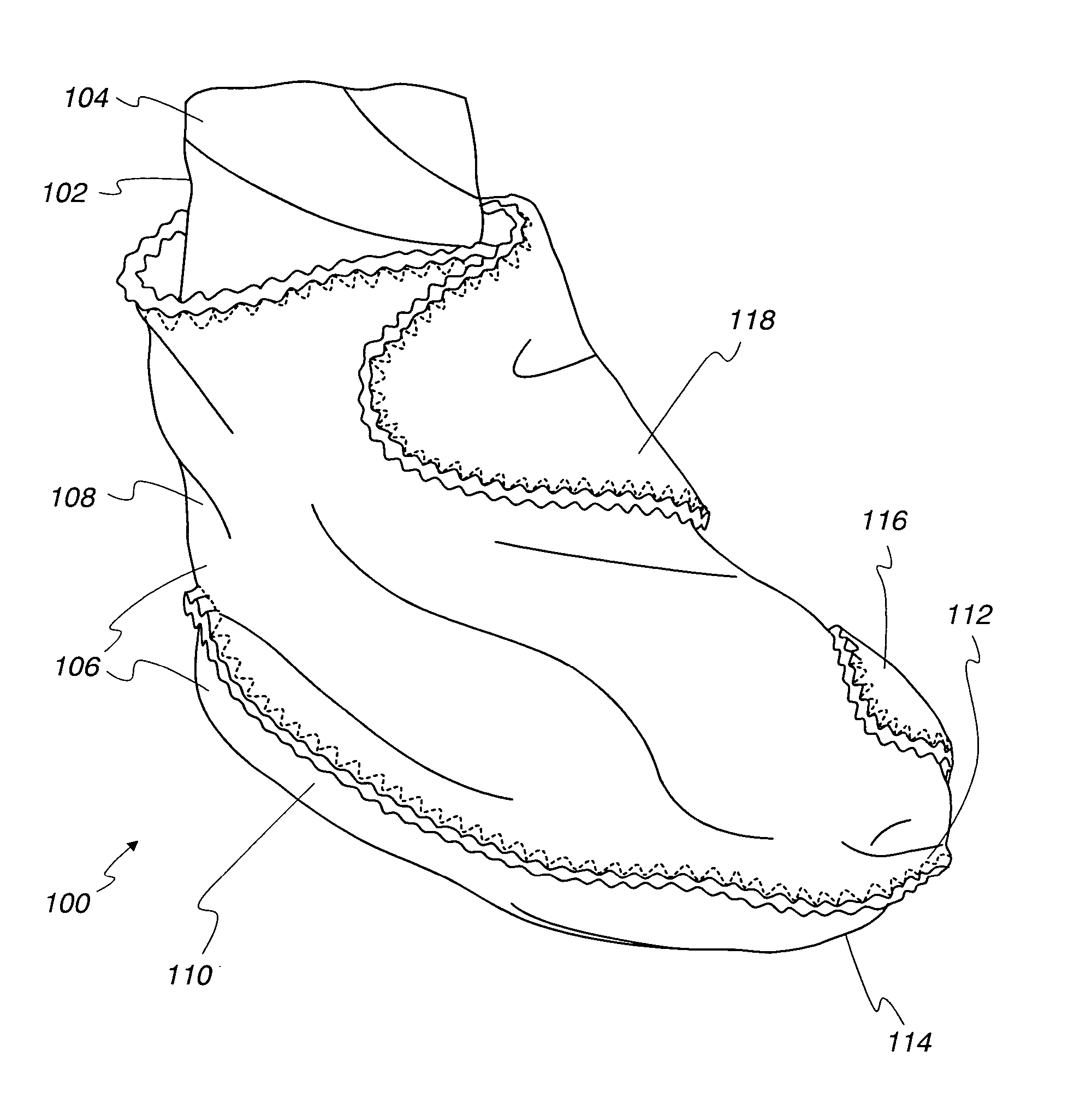
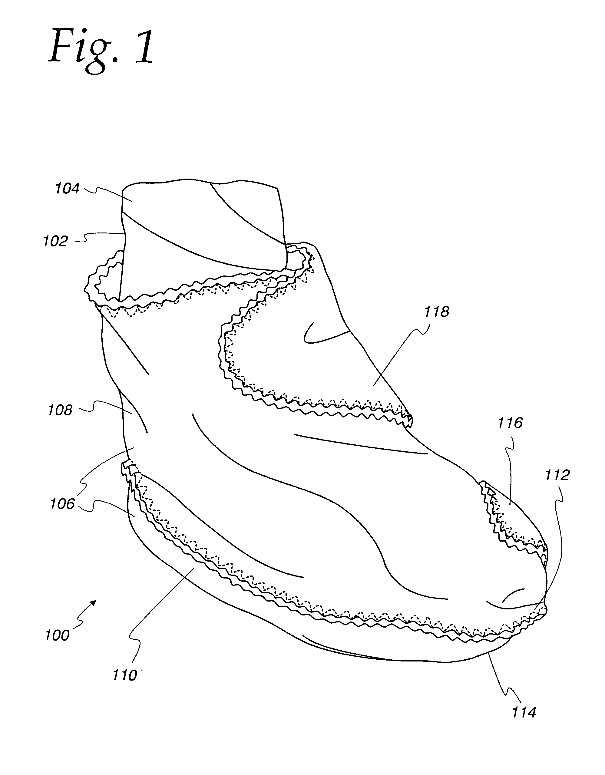
[0013] With reference to the drawings, FIG. 1 illustrates a slipper designed in accordance with an embodiment of the present invention in position on a leg 102 of one who may, for example, be a surgical patient, or one with a leg irritation or sore, or one who simply wants to keep his or her feet warm or who simply needs slippers.

[0014] As can be seen, this embodiment is a slipper 100 that is designed to wrap its insulating material around a leg 102. The leg 102 may possibly being bandaged with a bandage 104 that may be quite oddly shaped and bulky, in accordance with the nature of the surgery. Or, in the case of a fracture or sprain, the leg may be wrapped or in a cast, or it may simply be very swollen, and there may be no bandage or cast.

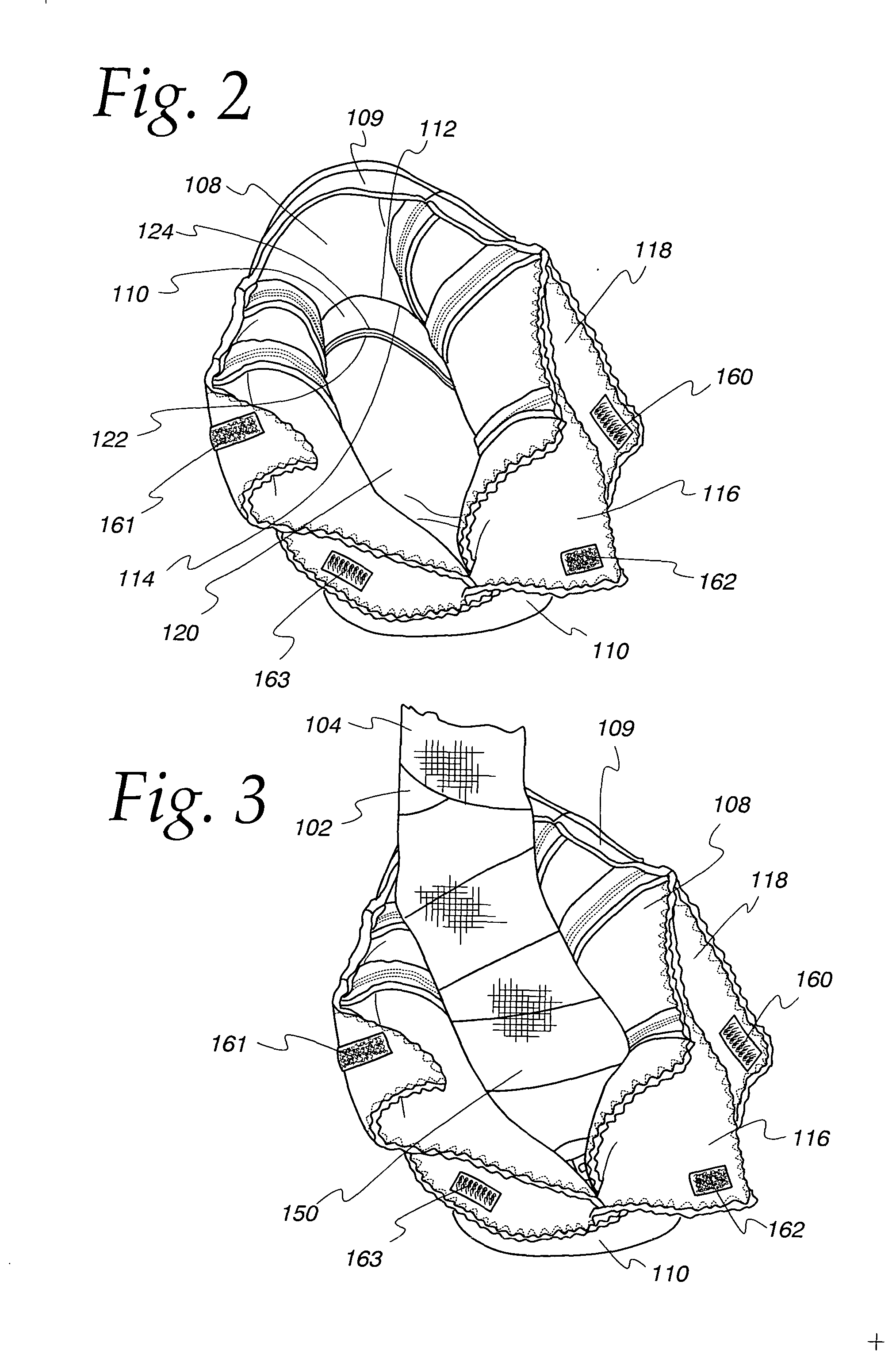
[0015] As seen in FIG. 1, the slipper 100 comprises an upper member 106 and a sole 120 (not shown in FIG. 1). The upper member 106, as is shown in FIG. 1, is formed from a spat 108 and a belt 110. The upper member 106 has an inner surface that i...


PUM


Abstract

A slipper designed to keep warm the foot of a patient with a foot injury, a patient recovering from foot surgery, a person with chronically cold feet, or a person who lacks the small motor skills to put on regular shoes. The slipper, made from soft, cottony material with a non-slip bottom surface as its sole, has a sole attached to a belt which attaches to a spat that covers the in-step. Two flaps attached to the spat fold over on top of the other side of the spat and fasten together with long fasteners that give a very wide, gentle degree of comfort and warmth to the foot.

Description

FIELD OF THE INVENTION [0001] The present invention relates generally to heat-retaining footwear, and more particularly to heat-retaining slippers designed to be used by patients recovering from foot surgery, persons with chronically cold feet, or persons who lack the small motor skills to put on regular shoes. BACKGROUND OF THE INVENTION [0002] Foot surgery is often followed by a long, painful recovery period. After foot surgery, such as bunion surgery, hammer-toe correction, reconstruction, etc., the foot is typically extremely sensitive to touch and weight, as well as to cold and heat. Foot surgery often involves the insertion of steel stabilizing pins into the bones of the foot. These pins remain sticking out of the foot during recovery and any movement of them causes extreme pain to the patient. After surgery, the foot is typically encased in a partial cast, with the toes or other portions of the foot exposed. [0003] After foot surgery, the patient is often required to keep the...

Claims


Application Information

Patent Timeline
Patent Type & Authority Applications(United States)
IPC IPC(8): A43B1/00A43B3/10A43B7/34A43B23/28
CPCA43B1/00A43B1/0081A43B23/28A43B7/34A43B13/12A43B3/107
Inventor ALLEN, FARROKH
Owner ALLEN FARROKH
Why Eureka
Try Eureka