Optical pickup device employing magnet and tracking coil to drive objective lens in tracking direction
a technology of optical pickup device and tracking coil, which is applied in the direction of data recording, instruments, disposition/mounting of heads, etc., can solve the problems of reducing driving force, tracking sensitivity impairing the tracking performance of optical pickup device, and large force driven by the objective lens holder. to prevent the effect of reducing the driving for
- Summary
- Abstract
- Description
- Claims
- Application Information
AI Technical Summary
Benefits of technology
Problems solved by technology
Method used
Image
Examples
first embodiment
[0037] First Embodiment
[0038] The present embodiment relates to a suitable arrangement of a tracking coil.
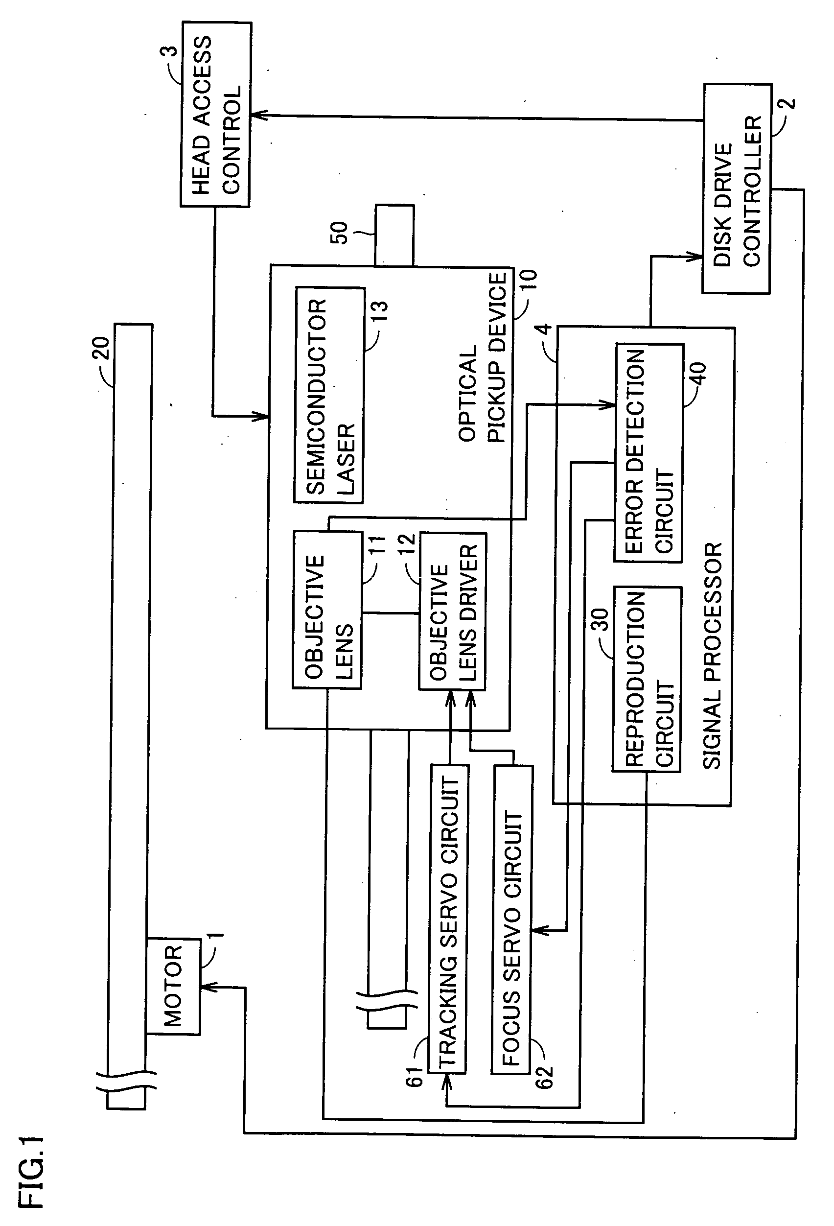
[0039]FIG. 1 schematically shows a configuration of an optical disk reproduction apparatus in accordance with the first embodiment. With reference to the figure, the optical disk reproduction apparatus includes a motor 1, a disk drive controller 2, a head access controller 3, a signal processor 4, an optical pickup device 10, a tracking servo circuit 61, a focus servo circuit 62, and a guide 50.
[0040] Motor 1 receives a control signal from disk drive controller 2 to rotate an optical disk 20 at a prescribed rate of rotation.
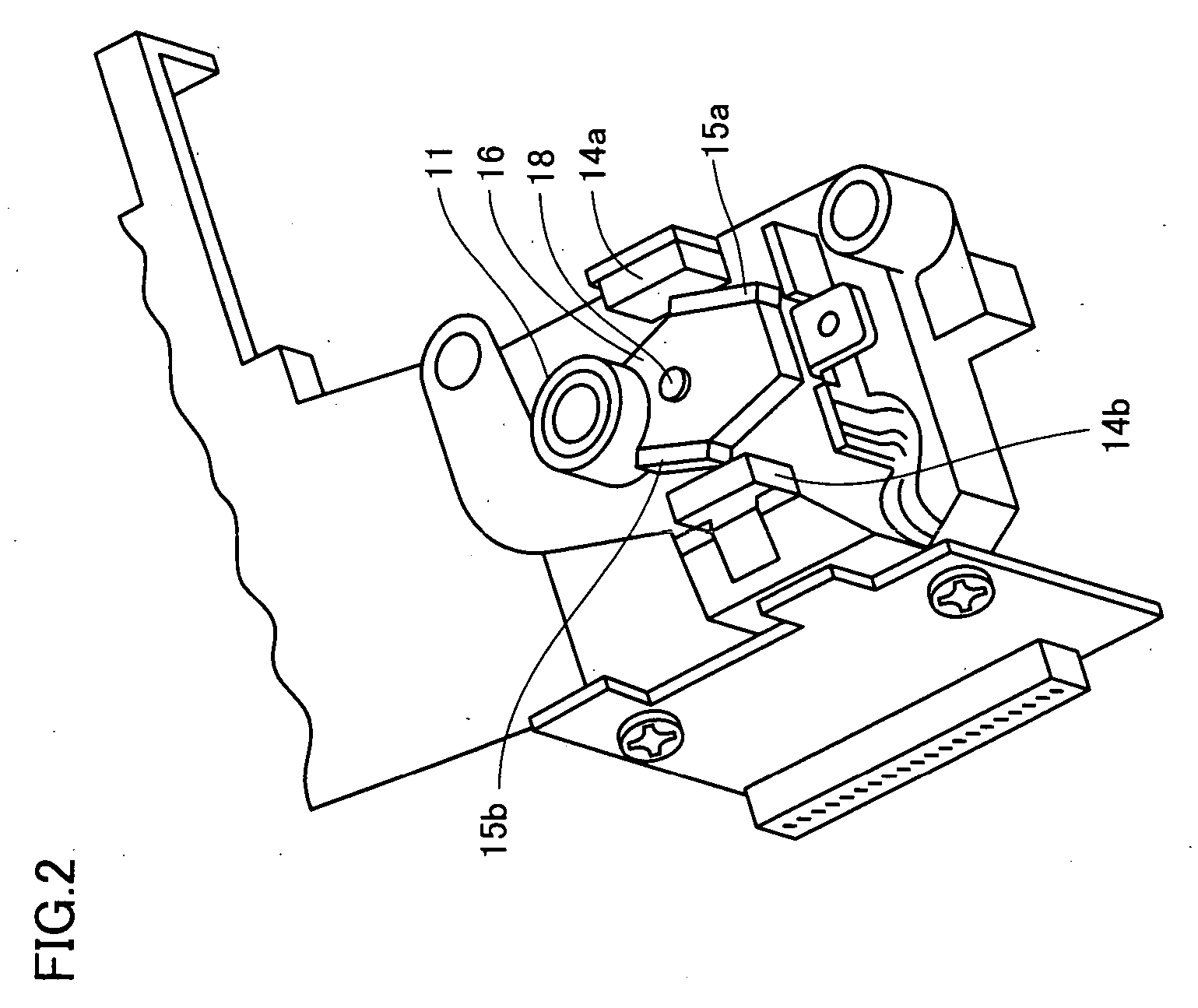
[0041] Optical pickup device 10 is driven by head access controller 3 along guide 50 in the optical disk 20a radial direction. Optical pickup device 10 includes a semiconductor laser 13 that serves as a source of light, an objective lens 11 that receives laser light output from semiconductor laser 13 and collects the light on optical disk 20 at a recording...
second embodiment
[0057] Second Embodiment
[0058] The present embodiment relates to a suitable geometry of the tracking coil.
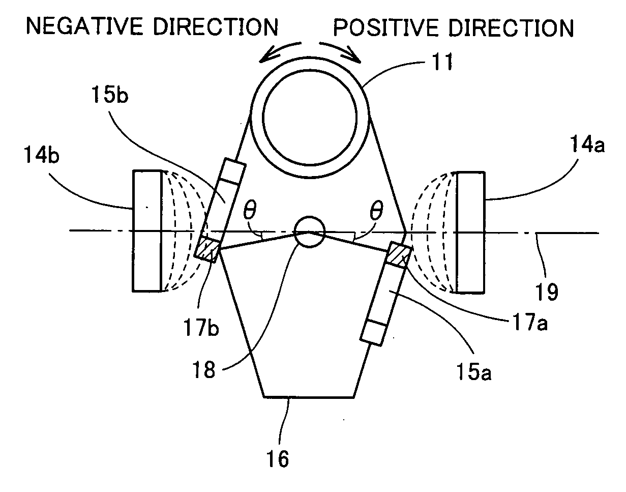
[0059]FIG. 6 is a cross section showing an arrangement of the tracking coils in the present embodiment and FIG. 7 is a perspective view showing an arrangement and geometry of the tracking coils in the present embodiment. In the figures, centerline 19 passes through magnets 14a and 14b at their respective centers. When objective lens 11 is not displaced in the tracking direction (i.e., when objective lens holder 16 is not rotating) a tracking coil 25a has a vertical portion 27a at a position distant from centerline 19 in a positive direction by a prescribed angle θ and a tracking coil 25b has a vertical portion 27b at a position distant from centerline 19 in a negative direction by the prescribed angle θ.
[0060]FIG. 8 specifically shows a geometry of tracking coil 25a. As shown in the figure, tracking coil 25a is an air core coil trapezoidal in geometry. More specifically, track...
third embodiment
[0073] Third Embodiment
[0074] The present invention relates to a suitable geometry of the tracking coil.
[0075] In the second embodiment a vertical portion (in FIG. 8, vertical portion 24a, 24b) opposite a vertical portion (in FIG. 8, vertical portion 27a, 27b) is sufficiently distant from a magnet, and the force generated at the opposite vertical portions can be neglected. If such an opposite vertical portions is insufficiently distant from a magnet, however, the opposite vertical portion experiences an unexpected force, and the objective lens is driven in the tracking direction by a variable force and can thus not be controlled. The present invention relates to a geometry of the tracking coil to avoid such an unexpected force.
[0076]FIG. 10 is a perspective view showing an arrangement and geometry of tracking coils in the present embodiment. As shown in the figure, similarly as has been described in the second embodiment, when objective lens 11 is not displaced in the tracking dir...
PUM
| Property | Measurement | Unit |
|---|---|---|
| magnetic field | aaaaa | aaaaa |
| electric current | aaaaa | aaaaa |
| magnetic fields | aaaaa | aaaaa |
Abstract
Description
Claims
Application Information
 - R&D
- Intellectual Property
- Life Sciences
- Materials
- Tech Scout
- Unparalleled Data Quality
- Higher Quality Content
- 60% Fewer Hallucinations
Browse by: Latest US Patents, China's latest patents, Technical Efficacy Thesaurus, Application Domain, Technology Topic, Popular Technical Reports.
© 2025 PatSnap. All rights reserved.Legal|Privacy policy|Modern Slavery Act Transparency Statement|Sitemap|About US| Contact US: help@patsnap.com


