
Illuminated personal safety device for use by cyclists and joggers

a personal safety device and illumination technology, applied in the field of illumination devices, can solve the problems of not being optically activated, bicyclist accidents occur with a high degree of frequency, and it is normally quite difficult for car drivers to see and avoid bicyclists

Inactive Publication Date: 2005-02-03
SEMINARA DOMINICK M +1
View PDF53 Cites 25 Cited by
  • Summary
  • Abstract
  • Description
  • Claims
  • Application Information

AI Technical Summary

Benefits of technology

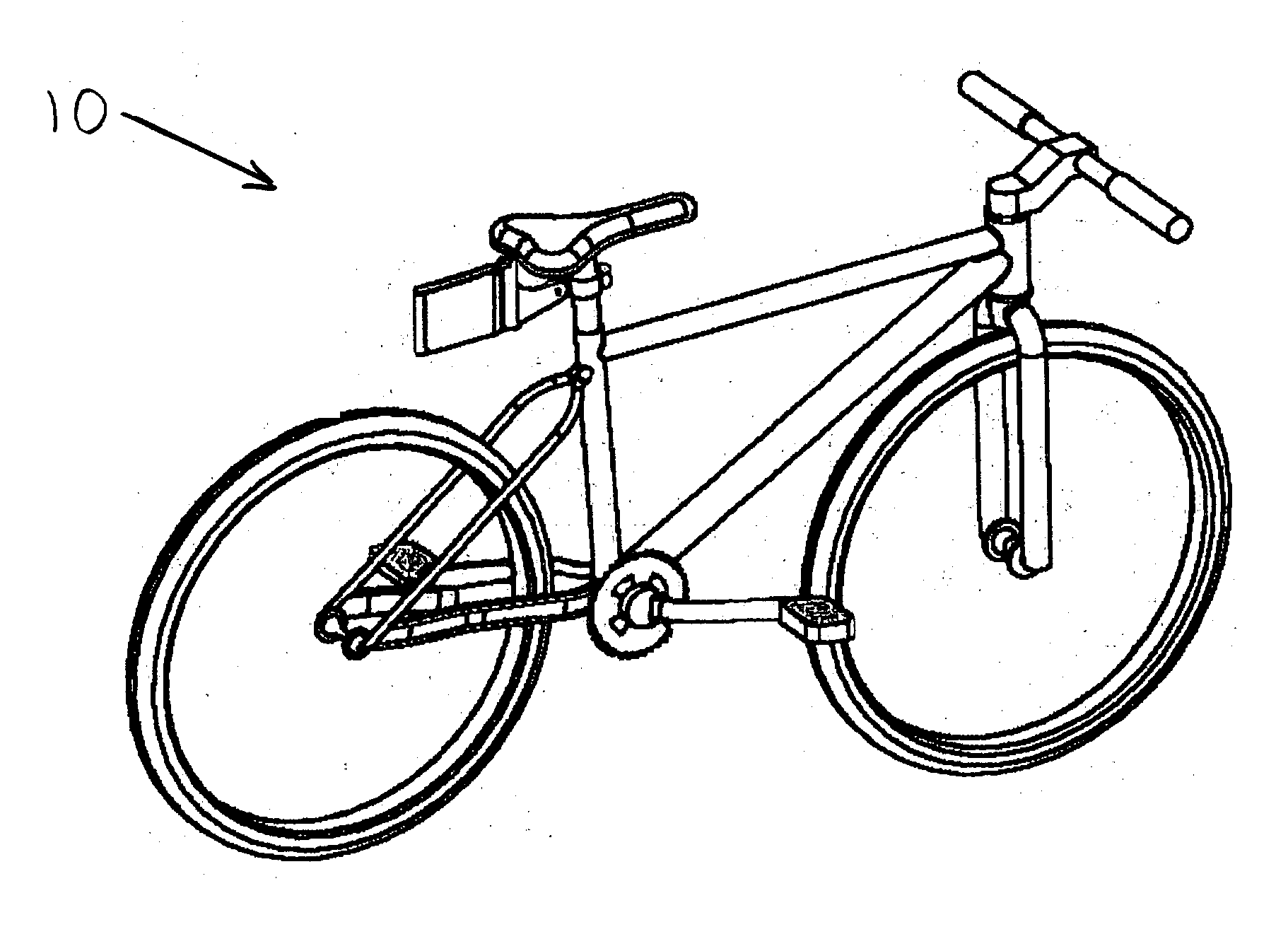
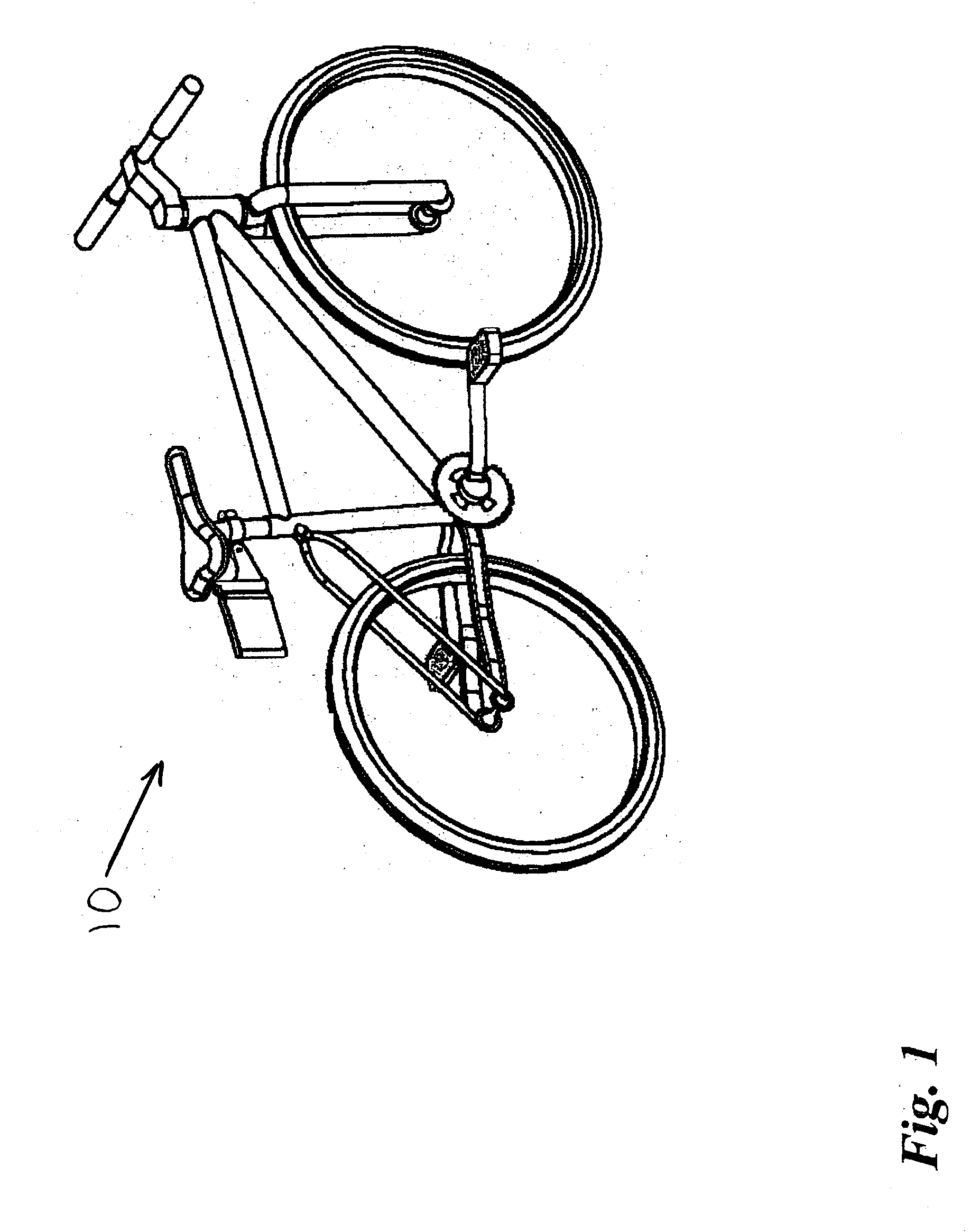
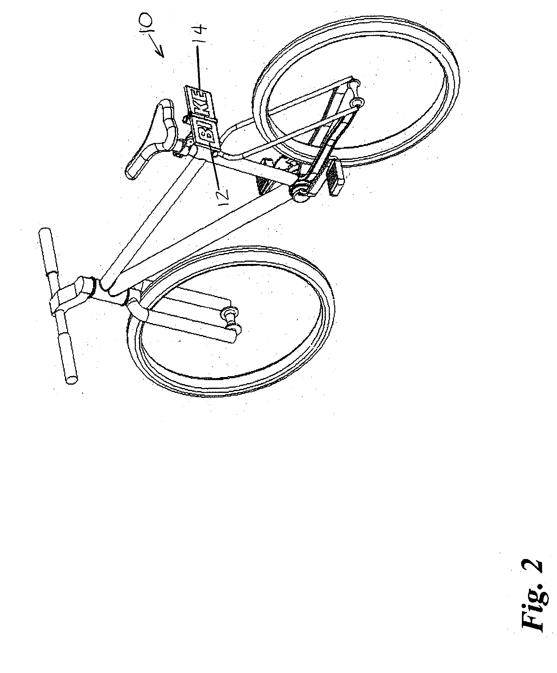
[0014] The present invention overcomes the limitations and disadvantages present in the art by providing a battery powered illuminated safety device adapted for attachment to a bicycle or scooter, or worn by a jogger at night. The safety device includes a pair of pivotally connected illuminated panels configurable between a compact stored configuration wherein the panels are disposed in substantially adjacent overlapping relation to a deployed configuration wherein the panels form a generally rectangular display. In the deployed configuration light-emitting devices, such as LED'S, f

Problems solved by technology

Serious injury, or even death, can result when a child riding a bicycle or foot scooter is struck by a car.
Bicycle accidents occur with a high degree of frequency particularly at night, for bicycle riders often share the same roads with vehicular traffic.
Hence, it is normally quite difficult for car drivers to see and avoid bicyclists.
The problem with a prism-type reflector is two-fold; for not only is its normal placement below the seat of the bicycle and therefore not easily discernible to a driver of a vehicle behind the bicyclist, but it is not optically activated unless the headlight beam of the vehicle directly strikes the reflector.
The drawbacks associated with the use of reflectors has been known for quite some time, thus lights have been incorporated into some bicycles.
Another disadvantage of such lights is that unless lights are attached to all four sides of the bicycle, a driver approaching the bicycle may not be able to view the light.
However, a driver approaching from the front of the bicycle will be unable to see the rearwardly directed light.
Yet another problem with such lights is that they are typically comprised of an incandescent lamp that requires a significant amount of power and is subject to breakage due to the shocks and jolts experienced during the riding of the bicycle.
The normal life span of such lights is also fairly limited, even absent such shocks and jolts.
Foot scooters, which are typically smaller than bicycles, have traditionally been devoid of such reflectors and lights, increasing the risk of injury, particularly at night.
The prior art fails to disclose an effective illuminated safety light for use by cyclists and / or joggers that incorporates an illuminated safety display and tilt switch actuated blinker lights.

Method used


Image

  • Illuminated personal safety device for use by cyclists and joggers
  • Illuminated personal safety device for use by cyclists and joggers
  • Illuminated personal safety device for use by cyclists and joggers

Examples


first embodiment

[0033] In a first embodiment depicted in FIGS. 6 and 7, light emitting devices 30 may be contained within panels 12 and 14 so as to provide backlighting for signal panels 22 and 24 thereby illuminating the display wording, warning signals, or any other suitable indicia. As disclosed herein above, light emitting devices 30 illuminate only when panels 12 and 14 are configured to the open configuration. In another embodiment shown in FIG. 9-11, a plurality of LED'S 30 are configured into letters that combine to spell “BIKE”, or any other suitable word(s) or signal.

second embodiment

[0034] In a second embodiment depicted in FIG. 8, panels 12 and 14 may further incorporate distal end portions, referenced as 40 and 42, configured with LED'S or lamps 30, which function as illuminated turn signals. Specifically, panels 12 and 14 are each adapted with additional electronic circuitry, including conductors 32 configured to selectively illuminate the end portion thereof for providing an illuminated turn signal. The turn signals are automatically activated by means of first and second normally open electromechanical tilt switches, referenced 44L and 44R. More particularly, tilt switch 44L activates, thereby placing the light emitting devices in distal end 40 in electrical communication with battery power source 19, when safety device 10 is tilted to the left, as happens when the user leans into a left hand turn. Similarly, tilt switch 44R activates, thereby placing the light emitting devices in distal end 42 in electrical communication with battery power source 19, when...


PUM


Abstract

An illuminated safety device adapted for attachment to a bicycle or scooter, or worn by a jogger at night is disclosed. The safety device includes a pair of pivotally connected illuminated panels configurable between a compact stored configuration wherein the panels are disposed in substantially adjacent overlapping relation to a deployed configuration wherein the panels form a generally rectangular display. In the deployed configuration light-emitting devices such as LED'S, function to provide an illuminated display and illuminated signaling, including an illuminated word, such as “BIKE” or “JOGGER”, along with left and right blinker lights automatically actuated by a tilt switch. Accordingly, when the biker or jogger leans to turn left: or right, the corresponding left or right blinker is activated. In the stored configuration the electrical contact terminals disengage from the electrical contact with the battery power source, and the display surfaces are protected as the opposing display panels are pivotally folded in overlapping face-to-face relation.

Description

COPYRIGHT NOTICE [0001] A portion of the disclosure of this patent document contains material that is subject to copyright protection. The copyright owner has no objection to the facsimile reproduction by anyone of the patent document or patent disclosure as it appears in the Patent and Trademark Office patent file or records, but otherwise reserves all copyrights rights whatsoever.CROSS REFERENCE TO RELATED APPLICATIONS [0002] N / A STATEMENT REGARDING FEDERALLY SPONSORED RESEARCH OR DEVELOPMENT [0003] N / A BACKGROUND OF THE INVENTION [0004] 1. Field of the Invention [0005] The present invention relates to illumination devices, and more particularly to illuminated personal safety devices for use by those exercising or recreating outdoors, primarily joggers and bicyclists. [0006] 2. Description of Related Art [0007] Millions of people exercise by bicycling and jogging in the United States, and worldwide. In fact, it is estimated that there are over 20 million bicycles in the United Sta...

Claims


Application Information

Patent Timeline
IPC IPC(8): A41D13/01B62J6/00G08B5/00G09F21/04
CPCA41D13/01G09F21/04G08B5/004B62J6/005B62J50/25B62J45/4151G09F21/026B62J6/16B62J6/057
Inventor SEMINARA, DOMINICK M.ANTHONY, MICHAEL M.
Owner SEMINARA DOMINICK M
Learn More