
Interlocking component assembly system

a technology of interlocking components and assembly systems, which is applied in the direction of furniture joining, dismountable cabinets, fastening means, etc., can solve the problems of increasing assembly time, cost and frustration for users/assemblers, and low ease of assembly/disassembly

Inactive Publication Date: 2005-02-03
THAI UNIVERSAL OFFICE PRODS
View PDF21 Cites 10 Cited by
  • Summary
  • Abstract
  • Description
  • Claims
  • Application Information

AI Technical Summary

Benefits of technology

[0017] An additional and significant advantage of the present invention is that various connecting methods, concealed or exposed, can be utilized to meet different market manufacturing, construction and assembly processes. Moreover, the interlocking flat panel / frame manufacturing, construction and assembly process of the present invention can reduce component inventory levels by up to 70% depending upon the product unit type. Other associated business inventory investment costs can be reduced by utilizing common components to construct various industry unit products.
[0018] In accomplishing these and other objects of the present invention, there is provided an interlocking component assembly comprising a plurality of frame components and a plurality of panels, wherein each panel formed integrally with a respective frame to form a frame and panel component. Means interconnect a plurality of the assembled frame and panel components together. The interconnecting means comprise a channel formed along the entire periphery of each of the frame / panel components. During assembly the channel of a frame / panel component is inserted within a channel of another frame / panel component to lock the components together along the length thereof.
[0019] The size of a unit made according to the present invention depends upon the height, width and depth of the frame and panel components. The unit can be prepared to accept any one or more of a plurality of sub-components.
[0020] These and other objects, features, aspects, and advantages of the present invention will become more apparent from the following detailed description of the preferred embodiment relative to the accompanied drawings, in which:

Problems solved by technology

One disadvantage with the known methods is that ease for assembly / disassembly is low, often requiring numerous fasteners, tools and personnel to complete the project.
Furthermore, even if the number of fasteners is minimal with such assemblies, the mere presence of fasteners decreases the aesthetics of the completed product.
Thus, the use of separate fasteners increases assembly time, costs and frustration for the user / assembler.
Hence, the ease of assembly is decreased due to cost, time and effort expended by the user / assembler.
Although the container can be assembled without separate fasteners, the cooperative mounting means are complicated and the pieces are not interchangeable.
Moreover, each container is independent and although numerous containers can be stacked, no means are provided for fastening a plurality of containers together to build a unit.

Method used


Image

  • Interlocking component assembly system
  • Interlocking component assembly system
  • Interlocking component assembly system

Examples


Embodiment Construction

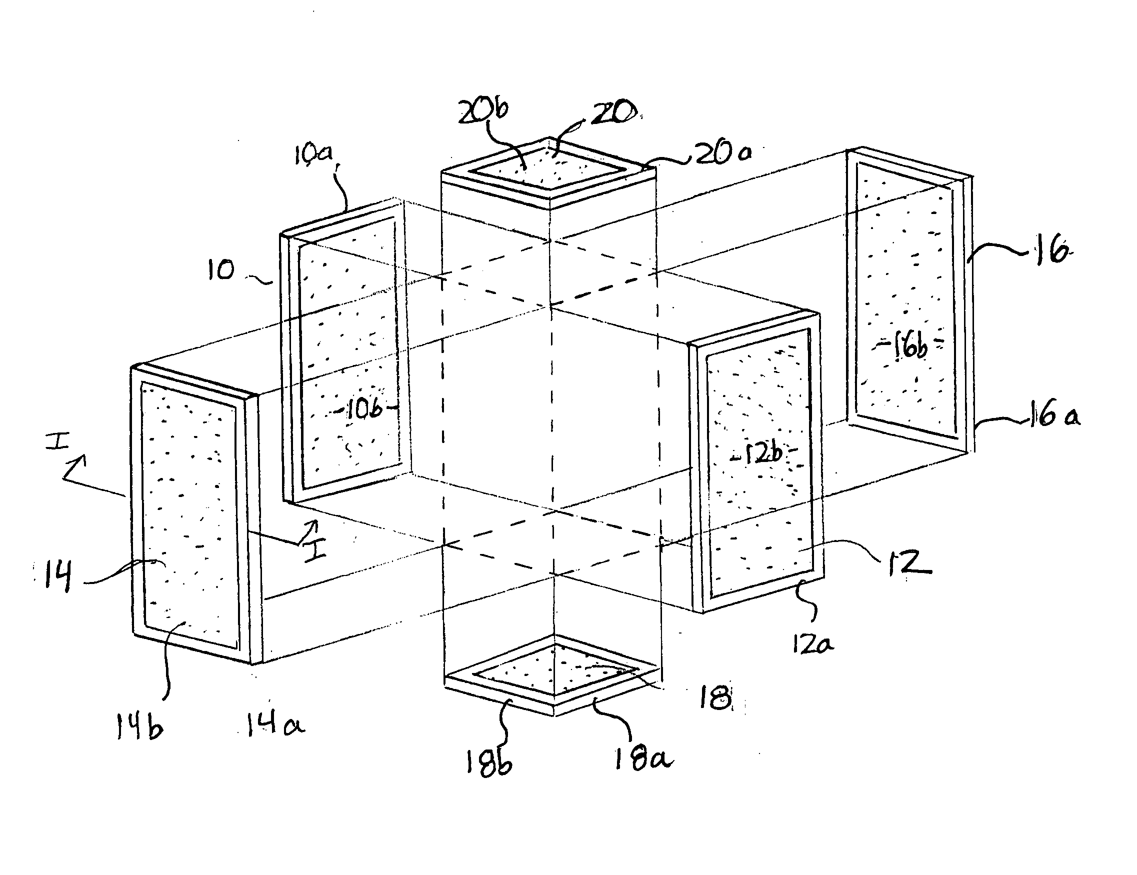
[0027] Referring to FIG. 1, a plurality of vertical interlocking flat panel / frame components 10, 12, 14 and 16 and horizontal interlocking flat panel / frame components 18 and 20 can be assembled to form an interlocking flat panel / frame unit according to the present invention. It should be appreciated that a variety of multi-sided or rectangular / square units can be assembled according to the present invention, with the specific shapes and sizes of the units being dictated by industry or customer requirements.

[0028] As shown in FIGS. 2a-2c, each vertical or horizontal component comprises an interlocking frame 12a, 18a and an integral flat panel 12b, 18b respectively. The panels and frames can be made of a variety of material, such as, metals, plastics, etc. The choice of material is dependent upon the industry (ANSI / BIFMA) requirements, as well as customer requirements such as function, cost, price point, etc. The frames 12, 18 are a unitary-channel shaped construction as described fu...


PUM

PropertyMeasurementUnit
angleaaaaaaaaaa
lengthaaaaaaaaaa
assembly timeaaaaaaaaaa

Abstract

An interlocking component assembly is made of a plurality of frame components and a plurality of panels. One panel is formed integrally with a respective frame to form a frame and panel component. A channel formed along the entire periphery of each of the frame components enables each of the frame and panel components to be interconnected. During assembly the channel of one frame component is inserted within a channel of another frame component to lock the components together along the length thereof. A plurality of locking tabs are disposed within the channel of each of the plurality of frame components. A plurality of apertures are also disposed within the channel of each of the plurality of frame components, wherein when the channel of a frame component is inserted within the channel of another frame component at least one locking tab is received within a corresponding aperture. This process is repeated until a three-dimensional unit is formed.

Description

BACKGROUND OF THE INVENTION [0001] 1. Field of the Invention [0002] The present invention relates to a flat panel / frame assembly of structural multi-sided units which can be assembled to form various industry products, and more particularly, to a method of assembling the multi-sided flat panel / frame cube units without additional, separate fasteners. [0003] 2. Description of the Related Art [0004] Precision assembly systems (P.A.S.), ready-to-assemble (R.T.A.) and knocked down (K.D.) methods for manufacturing, constructing and assembling square, multi-sided or rectangular cube based products are known. One disadvantage with the known methods is that ease for assembly / disassembly is low, often requiring numerous fasteners, tools and personnel to complete the project. Furthermore, even if the number of fasteners is minimal with such assemblies, the mere presence of fasteners decreases the aesthetics of the completed product. [0005] More often than not the fasteners are specially-config...

Claims


Application Information

Patent Timeline
Patent Type & Authority Applications(United States)
IPC IPC(8): A47B47/02A47B47/05A47B67/04F16B12/02F16B12/38
CPCA47B47/0075F16B12/38A47B47/05A47B47/02
Inventor BAKER, KEVIN
Owner THAI UNIVERSAL OFFICE PRODS
Learn More