
Video system

a video system and video technology, applied in the field of video systems, can solve the problems of conference interruption, troublesome both operators, etc., and achieve the effect of high performance and high use efficiency

Inactive Publication Date: 2005-01-27
CANON KK
View PDF19 Cites 92 Cited by
  • Summary
  • Abstract
  • Description
  • Claims
  • Application Information

AI Technical Summary

Benefits of technology

The present invention provides a video system with high use efficiency and performance. It includes a camera control system that allows for easy control of the camera's image pickup state through a communication means. The system can also store and change the image pickup state quickly for different needs. The camera control system can be connected to an external apparatus through communicating means, and the external apparatus can control the camera's image pickup means through the communicating means. The system can also display the image pickup signal on a multiwindow display function and control the focus and exposure of the image pickup means through the communicating means. Overall, the invention provides a convenient and efficient way to control the camera's image pickup state and achieve high-quality video images.

Problems solved by technology

There is consequently a problem such that both operators are troublesome and the conference is interrupted or the like.

Method used


Image

  • Video system
  • Video system
  • Video system

Examples


Embodiment Construction

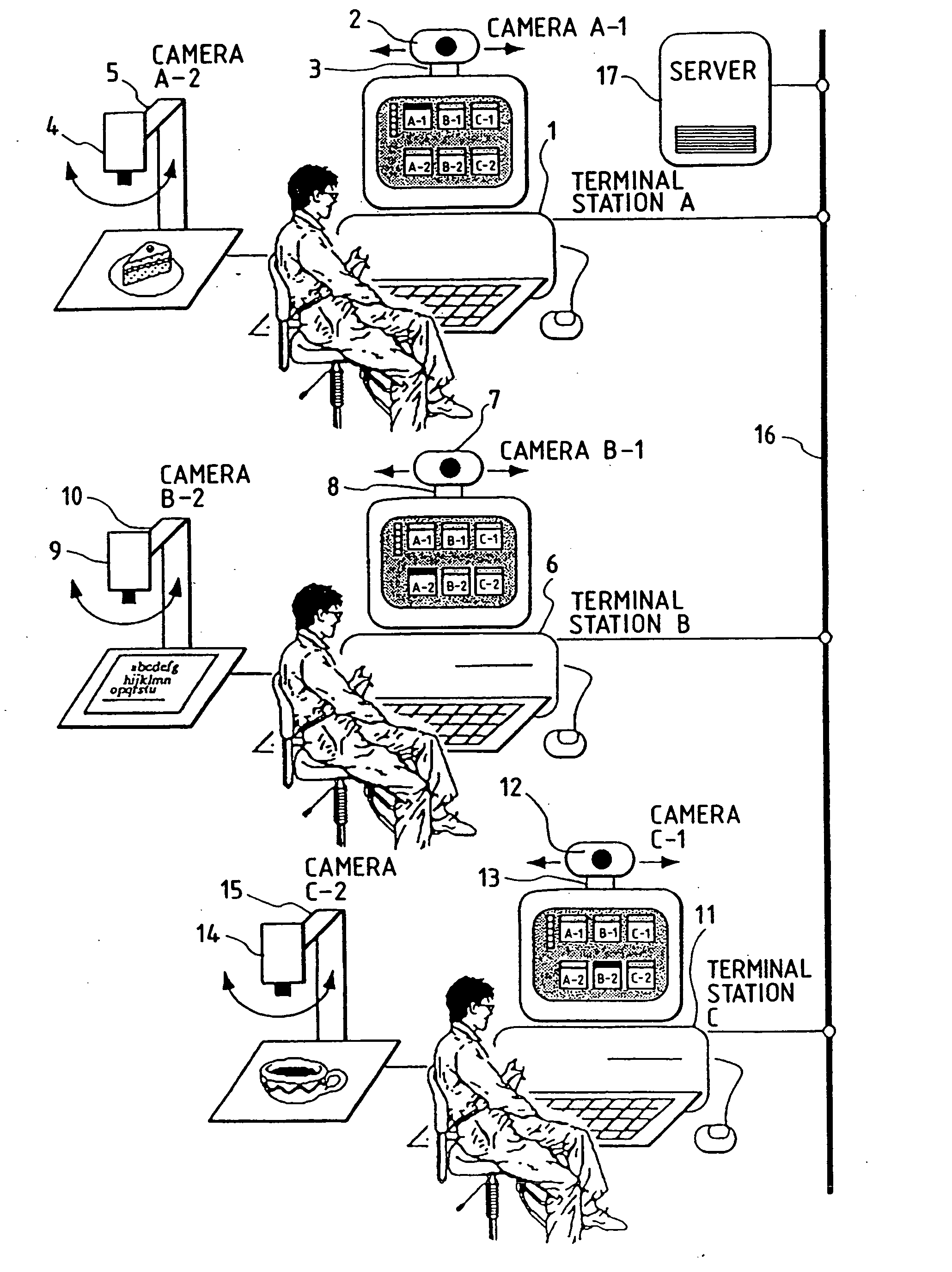
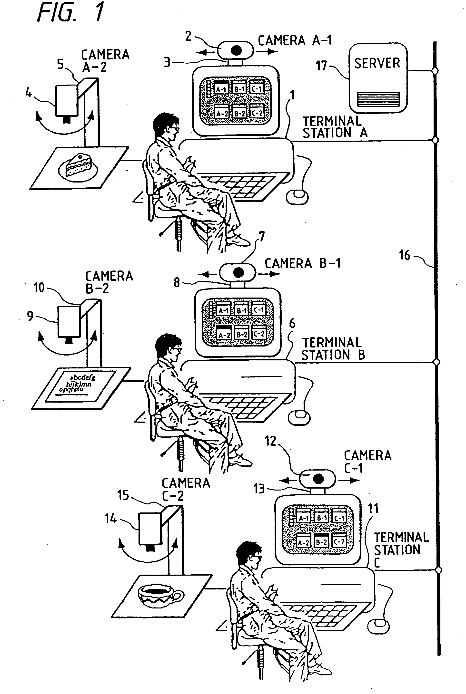
[0036]FIG. 1 is a schematic diagram showing an example of a whole construction of the invention.

[0037] In FIG. 1, reference numeral 1 denotes a first terminal station which is used in a multimedia teleconference and it is simply called a terminal A. Actually, it is not always necessary to use the terminal only for the multimedia teleconference but a personal computer or a workstation which has a bit map display and can display in multiwindows is used as a terminal. Reference numeral 2 denotes a camera for mainly photographing the face of a person and such a camera is hereinafter referred to as a camera A-1. Reference numeral 3 denotes a tripod to control the direction of the camera A-1; 4 indicates a calligraphic and pictorial camera for photographing an original, a printed matter, a solid object, or the like and such a camera is hereinafter referred to as a camera A-2; 5 indicates a movable arm for changing a photographing region of the camera A-2.

[0038] In a manner similar to th...


PUM


Abstract

In a video system of the invention, control means is provided for a terminal input apparatus which is connected by a communication network of a camera on the partner side and which comprises an image display apparatus having a multiwindow display function for selecting and displaying the camera. An image pickup operation which is required to the camera on the partner side, for example, the image pickup direction, focal distance, panning, exposure amount, white balance, automatic focusing, and the like of the designated camera are inputted by using an image display and a window display of the image display apparatus. The operation of the camera on the partner side and the operations of a tripod, a movable arm, and the like to hold the camera are controlled through communicating means. A photographed image is displayed by the display apparatus.

Description

BACKGROUND OF THE INVENTION [0001] 1. Field of the Invention [0002] The invention relates to a video system suitable for use in a teleconference or the like using an image through a multimedia network. [0003] 2. Related Background Art [0004] In recent years, a television conferencing system has been widespread due to a spread of high speed digital lines. As a typical construction of the conventional television conferencing system, there is a representative system such that exclusive-use terminals each comprising a video camera for displaying the face of a speaker and a video monitor are installed at two or more locations and the terminals are connected by lines of N-ISDN or the like. [0005] However, even if an exclusive-use video monitor is not used, moving images can be displayed on multiwindows owing to the recent realization of a high performance of a personal computer or a workstation. Therefore, a teleconference using moving images and voice sounds (hereinafter, the conference ...

Claims


Application Information

Patent Timeline
Patent Type & Authority Applications(United States)
IPC IPC(8): G09G5/00H04N7/14H04N7/15H04N23/40
CPCH04N7/147H04N7/142
Inventor SUGA, AKIRAMURAMOTO, TOMOTAKAIIJIMA, KATSUMIMITSUTAKE, HIDEAKISEKINE, MASAYOSHI
Owner CANON KK
Learn More