
Leverage hammer

a hammer and hammer head technology, applied in the field of fulcrum devices, can solve the problems of essentially losing the leverage provided by the curve on the head of the hammer, affecting the performance of the rip hammer when pulling out nails, and generally failing to achieve the fulcrum capability, etc., and achieves the effect of adding leverag

Inactive Publication Date: 2005-01-27
SLEIMAN TONY
View PDF7 Cites 13 Cited by
  • Summary
  • Abstract
  • Description
  • Claims
  • Application Information

AI Technical Summary

Benefits of technology

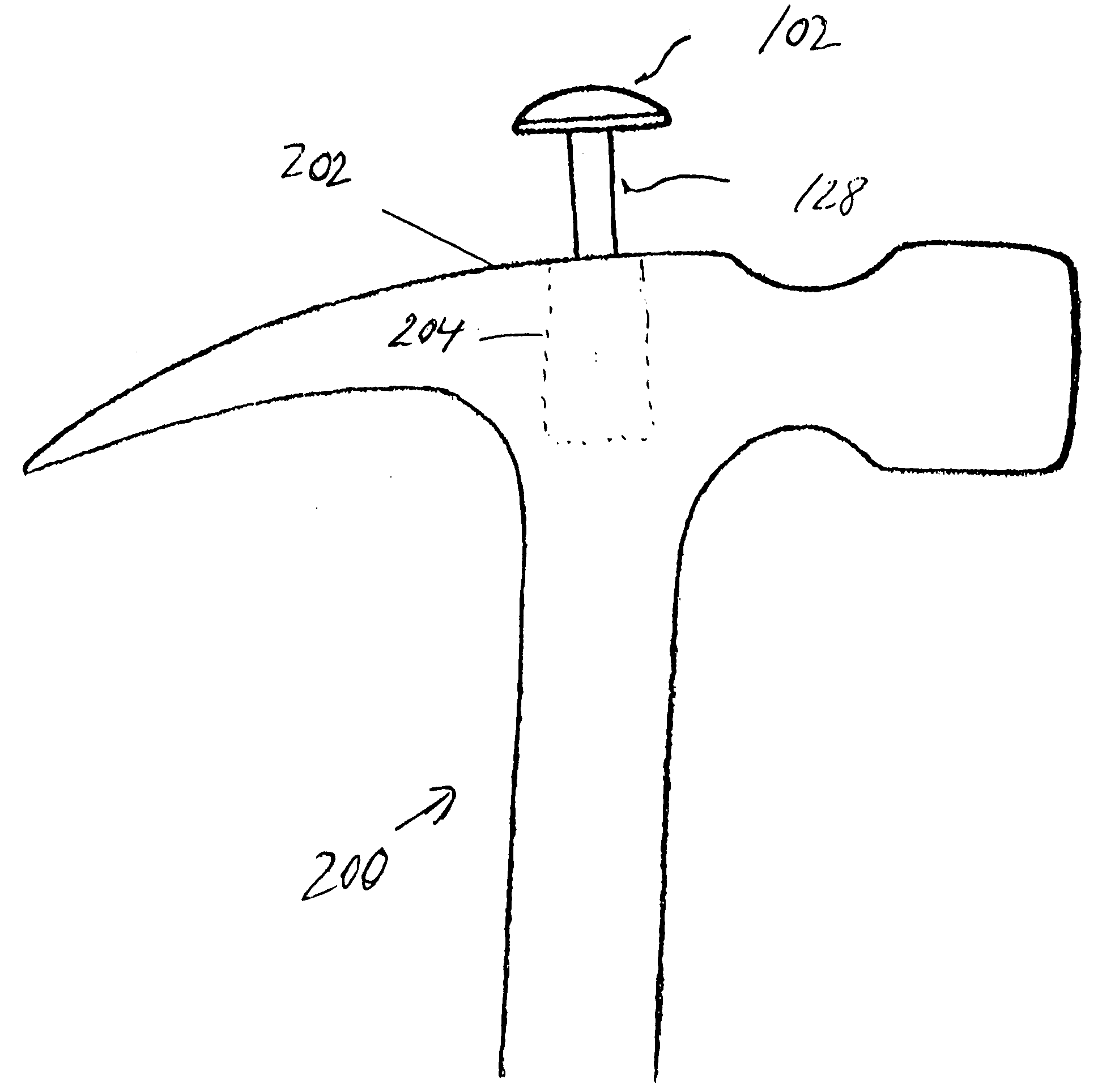
[0008] More specifically, the present invention is primarily directed to a selectively operable extendable fulcrum device that can be inserted into any type of hammer head (e.g., claw, rip, and the like) so as to provide additional leverage for, among other things, pulling out nails without resort to the use of another object placed under the head of the hammer.

Problems solved by technology

As the nail is pulled out far enough to cause the face portion of the head of the hammer to contact the work piece, the leverage that was provided by the curve on the head of the hammer is essentially lost.
Because the head of the rip hammer is relatively flat, it typically lacks the fulcrum capability that is needed to pull out nails, and, as a result, the rip hammer generally performs poorly when attempting to pull out nails.

Method used


Image

  • Leverage hammer
  • Leverage hammer
  • Leverage hammer

Examples


Embodiment Construction

[0025] The following description of the preferred embodiment(s) is merely exemplary in nature and is no way intended to limit the invention, its application, or uses.

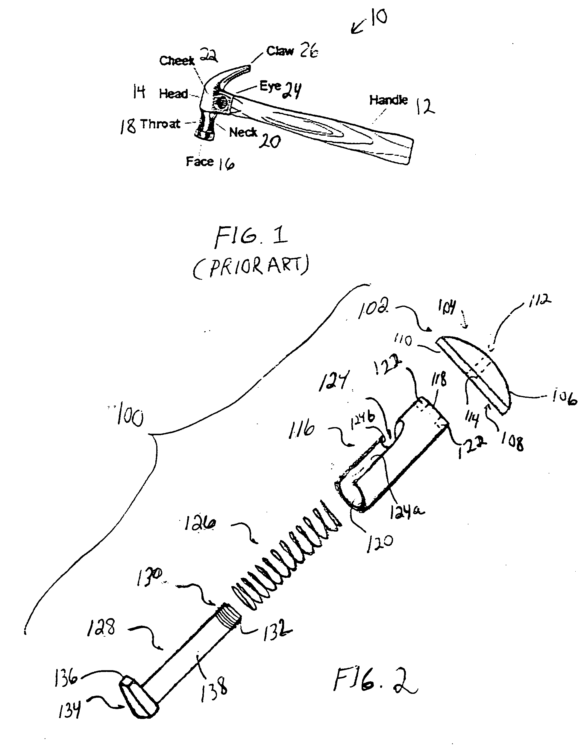
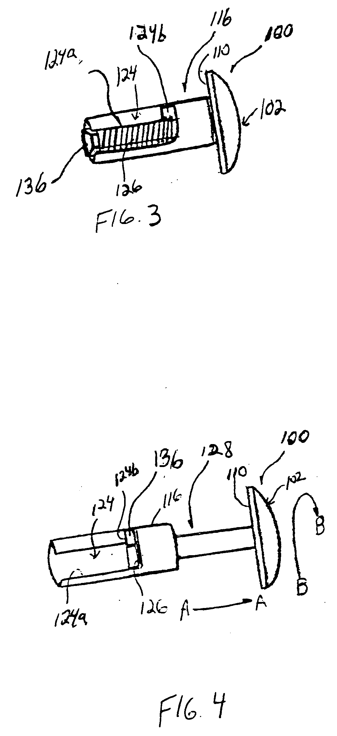
[0026] Referring to FIG. 2, there is shown a fulcrum device 100, in accordance with the general teachings of the present invention. The fulcrum device 100 preferably includes a fulcrum head 102 that preferably includes a first major face 104 that preferably has a substantially convex or rounded surface 106 formed thereon and an opposed second major face 108 that has a substantially flat surface 110 formed thereon. Along a central axis of the fulcrum head 102, an engagement surface 112, for example, a threaded surface 114, is preferably provided. The fulcrum head 102 may be comprised of any number of materials, but is preferably comprised of metallic materials.

[0027] A casing member 116 is preferably provided, wherein the casing member 116 is preferably comprised of a substantially hollow member. In accordance with a p...


PUM


Abstract

A selectively operable extendable fulcrum device is described. The device includes a casing with a slot to selectively guide and lock a selectively telescoping rod into place when extended. A ridge on the inside of the casing provides a resting place for a compression spring. The compression spring is operable to selectively retract the telescoping rod back into its retracted position and keeps the telescoping rod and fulcrum head assembly securely in place when retracted. The fulcrum head provides added leverage needed to pull out nails from materials when it is retracted as well as providing added leverage for longer nails when the fulcrum head is extended. The casing and the associated components of the device can be press fit into any conventional hammer head member.

Description

CROSS-REFERENCE TO RELATED APPLICATION [0001] This application claims the benefit of U.S. Provisional Patent Application Ser. No. 60 / 470,141, filed May 13, 2003, the entire specification of which is expressly incorporated herein by reference.FIELD OF THE INVENTION [0002] The present invention relates generally to fulcrum devices, and more particularly to a selectively operable extendable fulcrum device that can be at least partially disposed within the head of a hammer and is operable to extend out from the head of the hammer to provide added leverage needed to, among other things, pull nails out from material without the need for another object to be placed under the head of the hammer to provide the requisite amount of leverage. BACKROUND OF THE INVENTION [0003] Referring to FIG. 1, there is shown a claw hammer 10, in accordance with the prior art. The claw hammer 10 includes a handle member 12 and a head member 14. The head member 14 further includes a face portion 16, a throat p...

Claims


Application Information

Patent Timeline
Patent Type & Authority Applications(United States)
IPC IPC(8): B25D1/04
CPCB25D1/045
Inventor SLEIMAN, TONY
Owner SLEIMAN TONY
Learn More