
Combined musical instrument stand and workstation

a musical instrument and workstation technology, applied in the field of combined stringed musical instrument stands and workstations, can solve the problems of affecting the operation and the damage of instruments, and achieve the effect of convenient accessing the sid

Inactive Publication Date: 2005-01-27
KEMP KIM MARIE
View PDF7 Cites 26 Cited by
  • Summary
  • Abstract
  • Description
  • Claims
  • Application Information

AI Technical Summary

Benefits of technology

[0007] The second instrument-receiving portion is preferably pivotally mounted on the first instrument-receiving portion. The second instrument-receiving portion advantageously presents a surface which frictionally engages the neck of the instrument. The second instrument-receiving portion is conveniently substantially U-shaped. Twisting of the second instrument-receiving portion about the pivot mounting engages the neck of the instrument and hinders or prevents movement of the instrument parallel to the longitudinal axis of the first instrument-receiving means.
[0009] The stand and workstation preferably includes a base support adapted to support the base region of the instrument. The base support is conveniently adjustable to accommodate instruments of different sizes, to enable the workstation to be used for different makes and types of instrument. The base support preferably presents a surface which frictionally engages the base of an instrument to reduce movement of the instrument when the stand and workstation is in use.
[0012] The first support member is preferably pivotally mounted about its longitudinal axis to enable the instrument to be effectively held on its side, to enable the operative to more easily access the side of the instrument.

Problems solved by technology

However, when any work is to be carried out on the guitar such as changing strings, tuning or cleaning, it is usual to remove the guitar from the stand because the height, position and stability of the stand is not suitable for such operations.
Unfortunately, the instrument is then prone to being damaged due to accidental dropping or slipping and the operative is at a disadvantage due to having to use one hand to hold the instrument whilst carrying out the work required.

Method used


Image

  • Combined musical instrument stand and workstation
  • Combined musical instrument stand and workstation
  • Combined musical instrument stand and workstation

Examples


Embodiment Construction

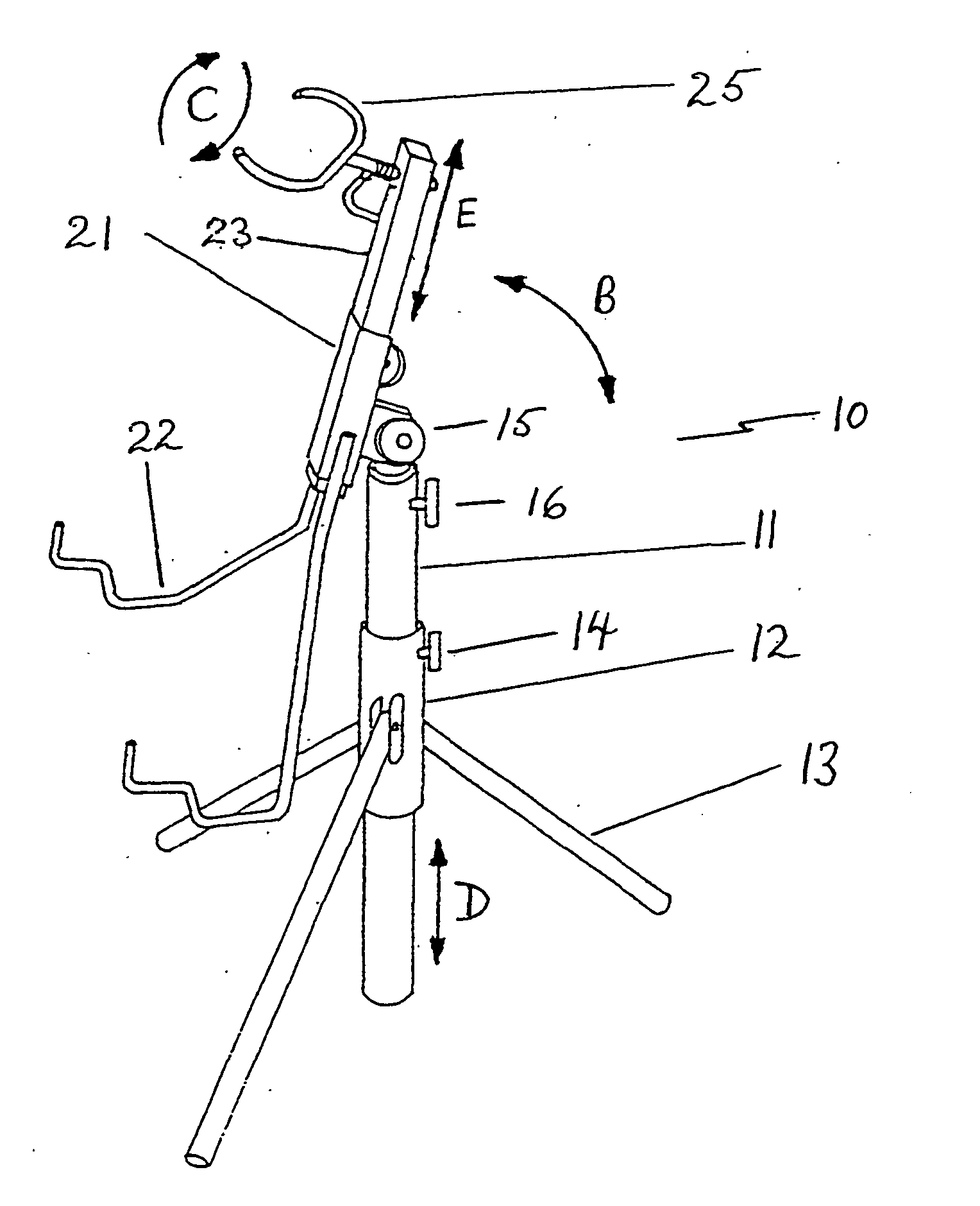
[0024] Referring initially to FIG. 1, the stand 10 has a central tubular support member 11. A tubular collar 12 is slidably mounted about the central support member 11. Further support for the stand 10 is provided by three legs 13, the legs 13 being pivotally mounted at one end to the collar 12. Once the angle of the legs has been established, relative to the central support member 11 which gives maximum stability to the stand 10, the legs 13 can be fixed in position by locking means (not illustrated). The position of the collar 12 on the central support member 11 is secured by engagement of the locking member 14 against the central support member 11.

[0025] A connection joint 15 is rotatably mounted to the upper end of the central support member 11, rotation being as indicated by arrows A in FIG. 2. A further locking member 16 fixes the connection joint 15 in its desired position. An instrument support frame generally referenced 20 is rotatably mounted to the connection joint 15. T...


PUM


Abstract

A combined stand and workstation (10) to support a stringed musical instrument such as a guitar or a banjo has an elongate receiving member (20) to support the instrument, the receiving member (20) being rotatably supported on support means (11). The support means (11) and the receiving member (20) are both adjustable in length. The receiving member (20) has supports (22, 25) for the base of the instrument and for its neck, and additionally can comprise an intermediate support to support the body of the instrument. The second instrument receiving portion (25) is rotatable and can be biased by means of a spring (27) to engage the neck of the instrument and prevent it from moving.

Description

FIELD OF THE INVENTION [0001] The invention relates to a combined stringed musical instrument stand and workstation which can be used to support an instrument in a substantially upright position when the instrument is not being played and which can be adjusted to support the instrument in a horizontal orientation or an inverted vertical orientation when required. BACKGROUND TO THE INVENTION [0002] Stands for stringed instruments particularly guitar-stands are well known and are widely used. They commonly comprise a frame with supporting legs on which are mounted supports for the base and neck of the guitar. The instrument is placed on the frame with the neck in a near vertical position, but tilted backwards so that gravity keeps the instrument retained on the supports. These stands are used to hold the instrument when not in use to prevent accidental mechanical damage. [0003] However, when any work is to be carried out on the guitar such as changing strings, tuning or cleaning, it i...

Claims


Application Information

Patent Timeline
IPC IPC(8): F16M11/20G10G5/00
CPCF16M11/20G10G5/00F16M11/046F16M2200/027F16M11/242F16M11/28F16M11/2021
Inventor KENT, KENNETH PAUL
Owner KEMP KIM MARIE
Learn More