
Carrier suppression type modulator with encoded modulating signals

a modulator and carrier type technology, applied in the field of carrier suppression type modulator and modulation arrangement, can solve the problems of ineffective burst-communication system, difficult to achieve and maintain precise adjustment, and high cost and complexity

Active Publication Date: 2005-01-20
NORTHROP GRUMMAN SYST CORP
View PDF18 Cites 6 Cited by
  • Summary
  • Abstract
  • Description
  • Claims
  • Application Information

AI Technical Summary

Benefits of technology

[0018] In one embodiment according to the invention, first and second modulators are serially coupled and a carrier is applied to the first modulator. An encoder forms a non-zero pseudo-random pattern signal as the modulating signal that is applied to the first modulator and the product of an information signal and a reciprocal of the non-zero pseudo-random signal as the modulating signal that is applied to the second modulator. The output o

Problems solved by technology

Such precise adjustment, however, is difficult to achieve and maintain under changing ambient conditions such as temperature, aging, and radiation effects.
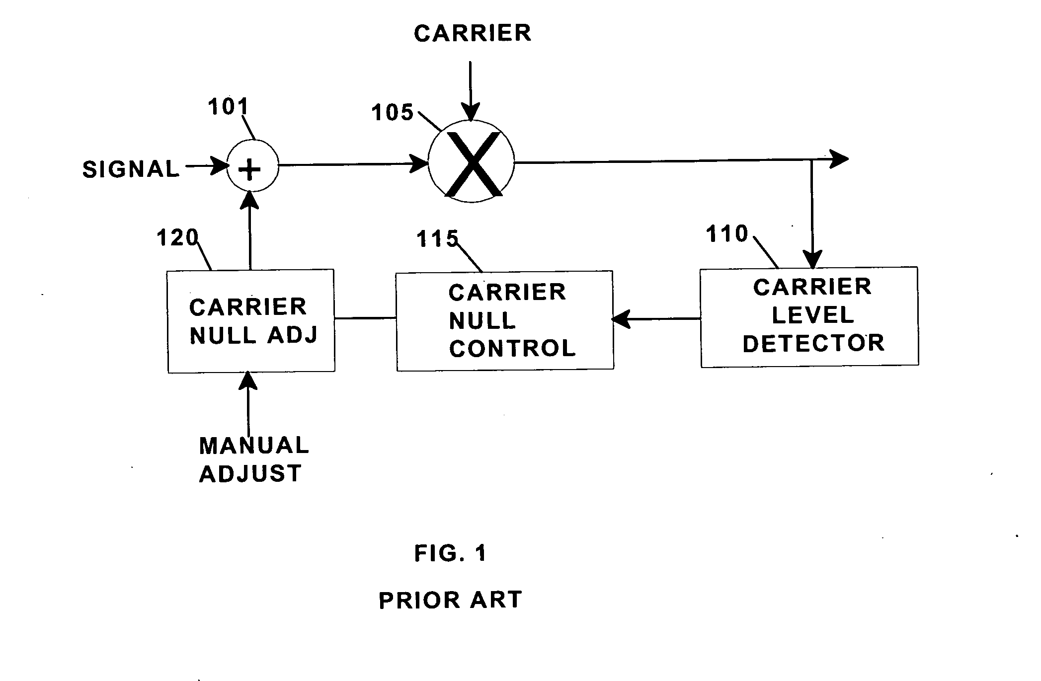
Such feedback arrangements are effective to provide carrier suppression without precise modulator adjustments but add significant complexity and cost.
The feedback arrangements also require settling time from turn-on until a satisfactory level of carrier suppression level is achieved and are ineffective for burst-communication systems.
The implementation of a feedback arrangement for carrier suppression, however, is subject to manual adjustment and requires added equipment and a significant setting time from turn-on.
In satellite and other communication systems where space, weight, and maintenance access are important, the added feedback type carrier suppression equipment is undesirable.
Accordingly, it is a problem to provide adequate carrier suppression without requiring either precise adjustment of transmitter parameters or the addition of feedback type carrier suppression equipment.

Method used


Image

  • Carrier suppression type modulator with encoded modulating signals
  • Carrier suppression type modulator with encoded modulating signals
  • Carrier suppression type modulator with encoded modulating signals

Examples


Embodiment Construction

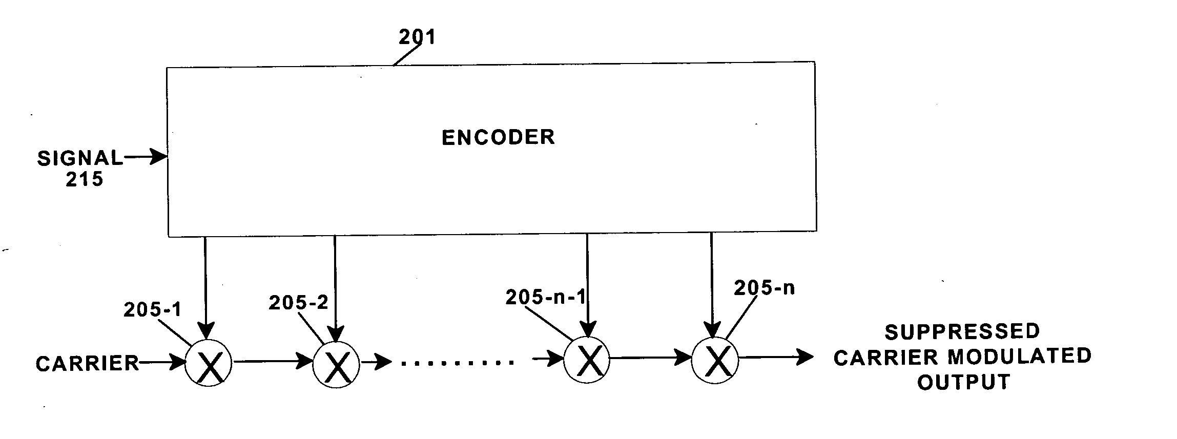
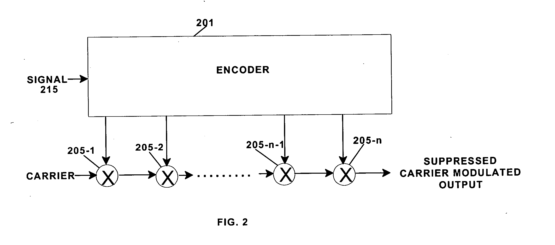
[0033] To provide carrier suppression of an RF modulator, it is necessary to precisely adjust the modulator characteristics to balance offsets in gain, phase and leakage. For a balanced modulator that uses I and Q inputs, carrier suppression is determined primarily by the DC voltage matching of the signals applied to the I and Q input stages of the modulator, the amplitude balance of the modulator and the carrier leakage. In accordance with the invention, plural modulators are serially coupled to further increase carrier suppression. FIG. 2 shows a general block diagram of a carrier suppression modulator according to the invention. In FIG. 2, there is shown an encoder 201 and serially coupled modulators 205-1, 205-2, . . . , 205-n−1 and 205-n. The serial coupled modulators, for example, may be real or complex analog or digital multipliers. A carrier is applied to a carrier input to modulator 205-1. The output of the modulator 205-1 is applied to the carrier input of modulator 205-2 ...


PUM


Abstract

A carrier suppressed information signal modulation arrangement employs a plurality of serially coupled carrier suppression modulators. Each of the serially coupled modulators has a carrier input, a modulating signal input and a modulated carrier output. A carrier is applied to the carrier input of the first modulator and the suppressed modulated carrier output of each modulator is coupled to the carrier input of the succeeding modulator. An encoder generates modulating signals to be applied to the modulating signal inputs of the serially coupled modulators in response to the information signal. The modulating signals applied to each of the serially coupled modulators modifies the modulated carrier output received at its carrier input to produce a suppressed modulated carrier at the output of the last of the serially coupled modulators that corresponds to the information signal.

Description

BACKGROUND OF THE INVENTION [0001] 1. Field of the Invention [0002] The invention relates to modulation systems and more particularly to modulation arrangements in which the carrier is suppressed. [0003] 2. Background of the Invention [0004] In many types of modulated transmission systems, a carrier modulated by an information signal is applied to a medium for transmission. The information signal may be analog or digital and of electrical or optical form. The power in the modulated signal is distributed among the carrier and modulation components. In satellite and other communication systems where the spectrum utilized for communication is crowded, the transmission power of individual channels is restricted to avoid inter-channel interference. To reduce the channel power without impairing information transmission, it is well known, to suppress the carrier component of the transmission signal. Such carrier suppression is important in making wideband frequency allocations to existing ...

Claims


Application Information

Patent Timeline
IPC IPC(8): H04L27/20H03C1/00H03D7/16H04K1/00H04L27/00H04L27/36
CPCH03D7/163
Inventor ATKINSON, LEONARD A.
Owner NORTHROP GRUMMAN SYST CORP
Learn More