Thermally-driven ink-jet printhead capable of preventing cavitation damage to a heater
a printhead and thermal drive technology, applied in the field of thermal drive inkjet printheads, can solve the problems of repeated cavitation damage, overheating of the printhead, severe damage, etc., and achieve the effects of preventing cavitation damage to the heater, improving structure, and improving structur
- Summary
- Abstract
- Description
- Claims
- Application Information
AI Technical Summary
Benefits of technology
Problems solved by technology
Method used
Image
Examples
first embodiment
[0065] In the present invention, inner surfaces of the first sidewalls 111 are uneven. Specifically, each of the first sidewalls 111 has at least one, or, more preferably, a plurality of, convex projection 113. As a result, a surface area of the inner surfaces of the first sidewalls 111 adjacent to a bubble formed in the ink chamber 106 increases, so that cavitation points move beyond outer edges of heaters 122 toward the first sidewalls 111. This operation will be subsequently described in further detail.
[0066] The first and second sidewalls 111 and 112 are formed of materials other than a material used to form the substrate 110. This selection is necessary because the ink chamber 106 is formed by isotropically etching the substrate 110 using the first and second sidewalls 111 and 112 as an etch stop. Thus, when the substrate 110 is formed of a silicon wafer, the first and second sidewalls 111 and 112 may be formed of silicon oxide.
[0067] The first and second sidewalls 111 and 112...
second embodiment
[0092]FIG. 11 illustrates a plan view of an ink-jet printhead according to the present invention. FIG. 12 illustrates a cross-sectional view of the ink-jet printhead taken along a line X2-X2′ of FIG. 11.
[0093] Referring to FIGS. 11 and 12, the structure of the ink-jet printhead according to the second embodiment of the present invention is substantially the same as the structure of the printhead shown in FIG. 6, except for a shape of a first sidewall 211. Thus, only the shape and function of the first sidewall 211 will be described below.
[0094] The ink chamber 106 is defined by the first sidewall 211 and a second sidewall 212 to have a substantially rectangular shape. A pocket 213 of the ink chamber 106 is formed in each of the first sidewalls 211, which are formed in a widthwise direction of the ink chamber 106. The pocket 213 opens toward a center of the ink chamber 106. Due to the pocket 213, when bubbles formed below the heaters 122 contract and collapse, the resultant cavitati...
third embodiment
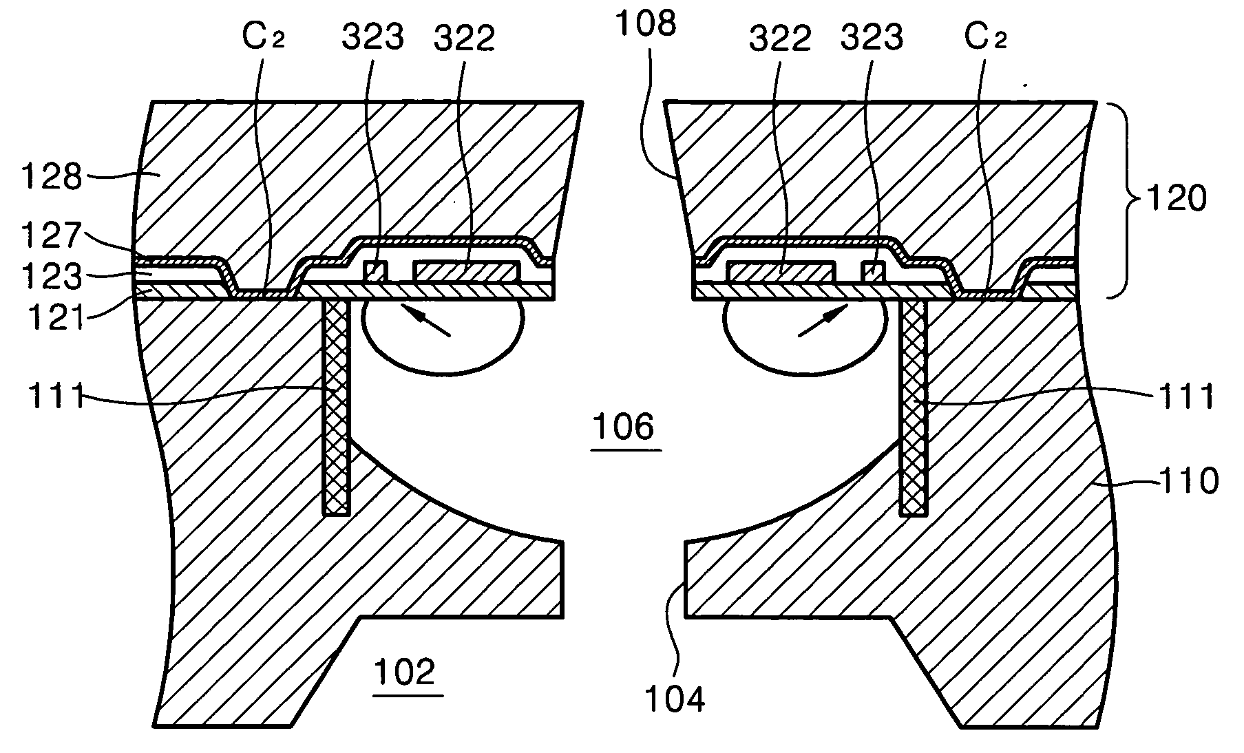
[0107] In the third embodiment, two main heaters 322 are disposed at opposite sides of the nozzle 108 above the ink chamber 106, which is defined by the first sidewalls 111 and the second sidewalls 112. Two auxiliary heaters 323 are disposed between each of the two main heaters 322 and a corresponding one of the first sidewalls 111 adjacent thereto. The main heaters 322 have a substantially rectangular shape having a longer length parallel to the first sidewalls 111. The auxiliary heaters 323 have a substantially rectangular shape and are disposed parallel to the main heaters 322. The main heaters 322 and the auxiliary heaters 323 may be formed of the same material as the material used to form the heaters according to the previously-described embodiments of the present invention.
[0108] One of the main heaters 322 and a corresponding one of the auxiliary heaters 323 are both connected to a conductor 324, so that a current may be simultaneously applied to the main heater 322 and the a...
PUM
 Abstract
Description
Claims
Application Information
 - R&D
- Intellectual Property
- Life Sciences
- Materials
- Tech Scout
- Unparalleled Data Quality
- Higher Quality Content
- 60% Fewer Hallucinations
Browse by: Latest US Patents, China's latest patents, Technical Efficacy Thesaurus, Application Domain, Technology Topic, Popular Technical Reports.
© 2025 PatSnap. All rights reserved.Legal|Privacy policy|Modern Slavery Act Transparency Statement|Sitemap|About US| Contact US: help@patsnap.com


