
Walk behind mower

Inactive Publication Date: 2005-01-20
WALKER MFG CO
View PDF17 Cites 3 Cited by
  • Summary
  • Abstract
  • Description
  • Claims
  • Application Information

AI Technical Summary

Benefits of technology

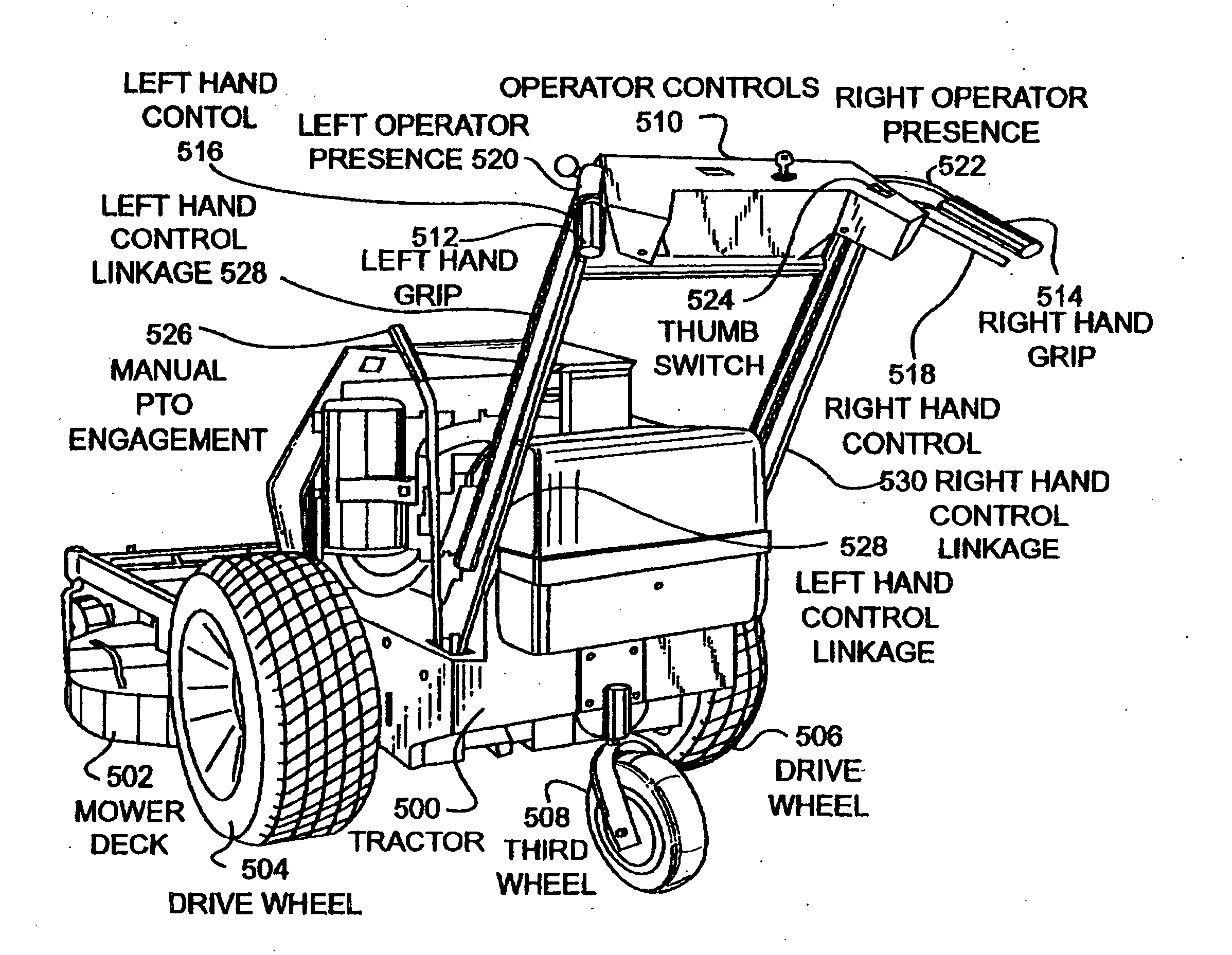
[0008] The present invention overcomes the disadvantages and limitations of the prior art by providing a mower that has a deck removably attached to a walk behind, self-propelled tractor. The tractor has a set of operator controls that includes a rocker switch that is used to set the forward speed of the tractor and two hand levers that are used to brake each wheel individually for steering. The tractor is propelled using individual hydrostatic drives on each of two main drive wheels and has a third wheel pivotally mounted rearwardly that provides stability to the tractor when no implements are attached. The tractor has an articulated mower deck mounted to the front. The arrangement is better able to closely follow the contour of the ground during mowing of uneven surfaces and places the operator controls in a more comfortable and controllable position.
[0012] The advantages of the present invention are that the mower is better able to follow the contour of the ground due to the articulated connection of the mower deck to the three wheeled tractor. Further, the positioning of the operator controls while following various ground contours is more comfortable and thus safer and less fatiguing. The control system for the mower allows for infinitely adjustable forward speed without requiring the operator to continually hold any handles other than an operator presence switch, further decreasing the fatigue of the operator.

Problems solved by technology

A serious disadvantage with such types of mowers is that the quality of cutting is not as good as desired, since the mower can ‘scalp’ the grass in some areas and leave the grass too long in other areas because the mowing deck is not able to closely follow the contour of the ground.
The operator controls for self-propelled walk behind mowers tend to be difficult to use while meeting the requirements of safety and operability.
Such a system is prone to operator fatigue.

Method used


Image

  • Walk behind mower
  • Walk behind mower
  • Walk behind mower

Examples


Embodiment Construction

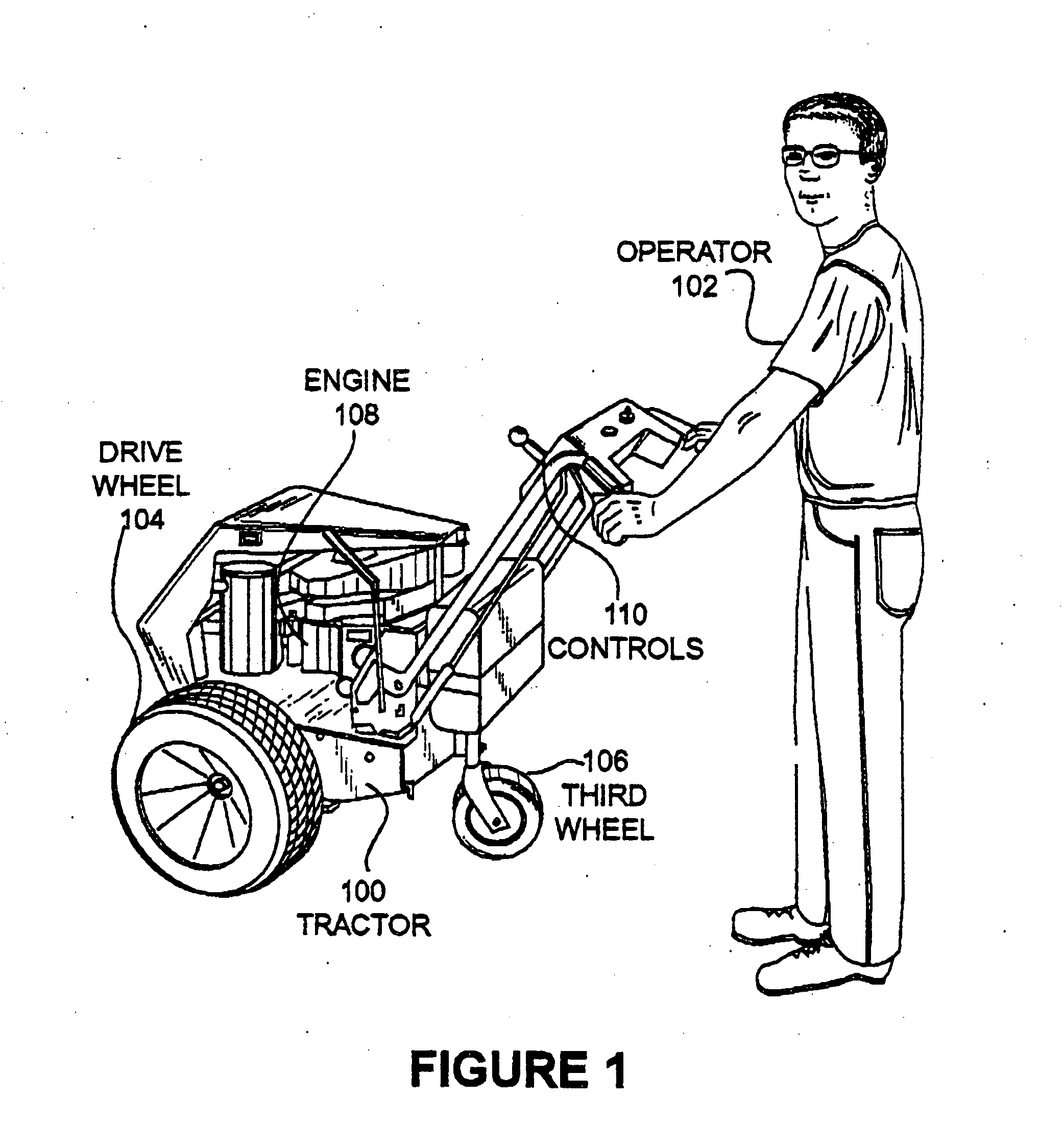
[0021]FIG. 1 illustrates an embodiment of the present invention showing a tractor 100 and an operator 102. The tractor 100 has a drive wheel 104 and a third wheel 106 that pivots but is not driven or steered. The engine 108 powers the tractor. The operator controls 110 are also shown in the present figure.

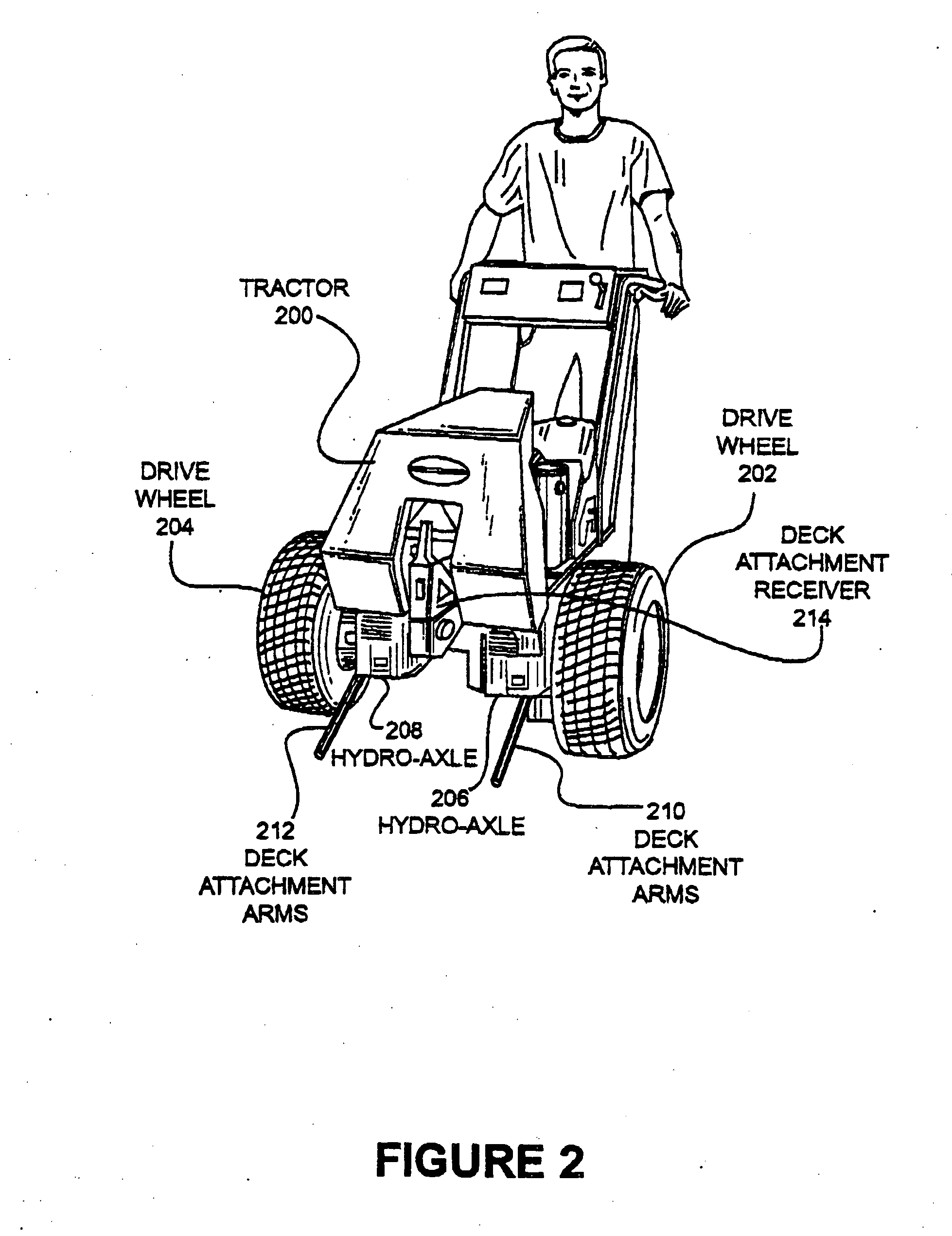
[0022]FIG. 2 illustrates a second view of an embodiment of the present invention showing a tractor 200, a first drive wheel 202, and a second drive wheel 204. The drive wheel 202 is powered by a hydro-axle 206 and drive wheel 204 is powered by hydro-axle 208.

[0023] The hydro-axles 206 and 208 are powered by an engine and are controlled by an operator to direct the movement of the tractor 200. The hydro-axles 206 and 208 may be capable of infinitely adjustable speed control based on the input from the operator. Steering is achieved through differential speeds applied to the drive wheels 202 and 204. The hydro-axles 206 and 208 may further be capable of reversing direction. In the ...


PUM


Abstract

Disclosed is a self propelled walk behind mower comprised of a tractor unit and a mowing deck. The tractor unit is hydrostatically driven with a unique control system whereby the forward speed of the tractor is set by operating an electric rocker switch with an operator's thumb. Hand levers are used to turn the tractor to the left and the right. The tractor unit comprises two drive wheels and a third wheel that is pivotally attached, letting the tractor unit stand upright when no implements are attached. Implements attach to the front of the tractor through a movable attachment so that the tractor and implement can closely follow the contour of the ground while keeping the operator controls in a convenient position.

Description

CROSS REFERENCE TO RELATED APPLICATIONS [0001] This application claims benefit of and priority to U.S. Provisional Patent Application Ser. No. 60 / 391,057 entitled “Walk Behind Mower” by Dean M. Walker, filed Jun. 21, 2002, the entire contents of which are specifically incorporated herein by reference for all it discloses and teaches.BACKGROUND OF THE INVENTION [0002] a. Field of the Invention [0003] The present invention pertains generally to walk-behind mowers and specifically to walk-behind mowers that have electric speed control. [0004] b. Description of the Background [0005] Walk-behind mowers including a tractor unit and a mowing deck attached to the front of the tractor have been commercially available for a long time. Typically, the tractor has only two wheels and the mowing deck is rigidly connected to the forward end of the tractor. A serious disadvantage with such types of mowers is that the quality of cutting is not as good as desired, since the mower can ‘scalp’ the gras...

Claims


Application Information

Patent Timeline
IPC IPC(8): A01B51/02A01D34/68B62D11/18B62D51/04
CPCA01B51/02A01D34/68B62D51/04B62D11/183A01D2101/00
Inventor WALKER, DEAN M.
Owner WALKER MFG CO
Learn More