
Window blind having multiple driving modes

a technology of window blinds and driving modes, applied in the field of window blinds, can solve the problems of inconvenient use of window blinds with exposed cord members, inability to eliminate elastic fatigue problems, and inability to use spring means or positioning cord members, etc., and achieve the effect of convenient control of the shading status of the blind body

Inactive Publication Date: 2005-01-20
NIEN MADE ENTERPRISE CO LTD
View PDF6 Cites 16 Cited by
  • Summary
  • Abstract
  • Description
  • Claims
  • Application Information

AI Technical Summary

Benefits of technology

[0006] It is the main object of the present invention to provide a window blind, which enables the user to control the shading status of the blind body conveniently.
[0007] It is another object of the present invention to provide a window blind, which has no cord member or string means exposed to the outside, preventing hanging of the exposed cord member or string means on a child accidentally.

Problems solved by technology

A window blind with exposed cord members is not safe in use because the exposed cord members are accessible to children, and an accident may happen when a child playing with the cord members for fun.
Therefore, window blinds with exposed cord members are not popularly acceptable at the present time.
The use of spring means or positioning cord member cannot eliminate the problem of elastic fatigue.
When the problem of elastic fatigue occurred, the spring means or positioning cord member can no longer support the bottom rail accurately in position.
It is not easy to connect the handle to the linking mechanism (because the end of the handle held by the user is the fulcrum, the positioning of the other end of the handle becomes unstable when the fulcrum vibrated with the user's hand.
Further, when driving the handle to turn the linking mechanism after connection of the handle to the linking mechanism, the handle may slip from the linking mechanism due to uneven application of force to the handle.
In general, the control of the prior art window blinds is not convenient.

Method used


Image

  • Window blind having multiple driving modes
  • Window blind having multiple driving modes
  • Window blind having multiple driving modes

Examples


Embodiment Construction

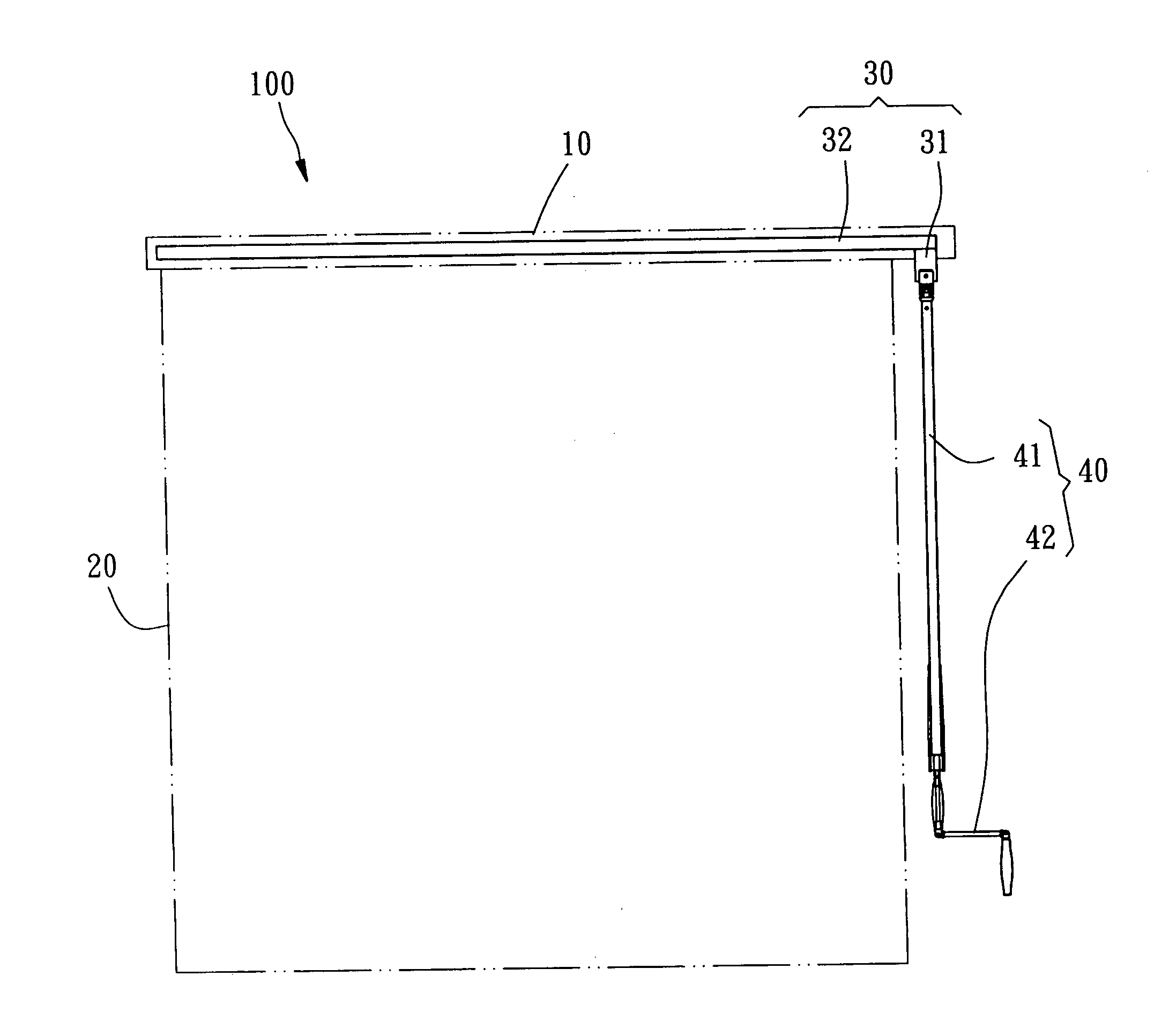
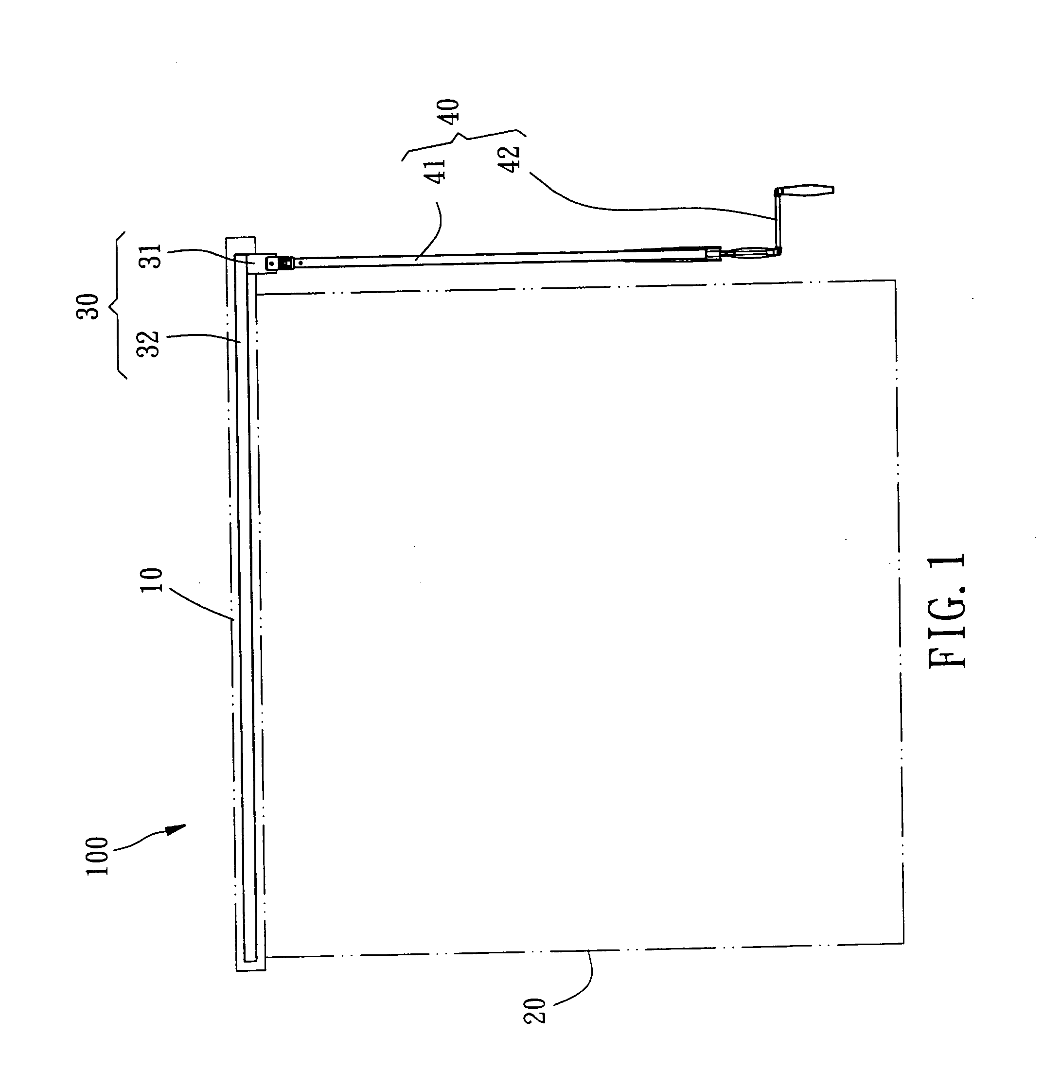
[0016] Referring to FIG. 1, a window blind 100 in accordance with the first preferred embodiment of the present invention is shown comprised of a headrail 10, a blind body 20, a linking mechanism 30, and a driving control mechanism 40.

[0017] The headrail 10 is transversely (horizontally) affixed to the top side of the window (not shown). The blind body 20 can be a slat set for Venetian blind or a curtain for a window covering. According to this embodiment, the blind body 20 is a piece of curtain suspended below the headrail 10 at the one side of the window inside the house, and controlled by an external drive force to change its window shading status.

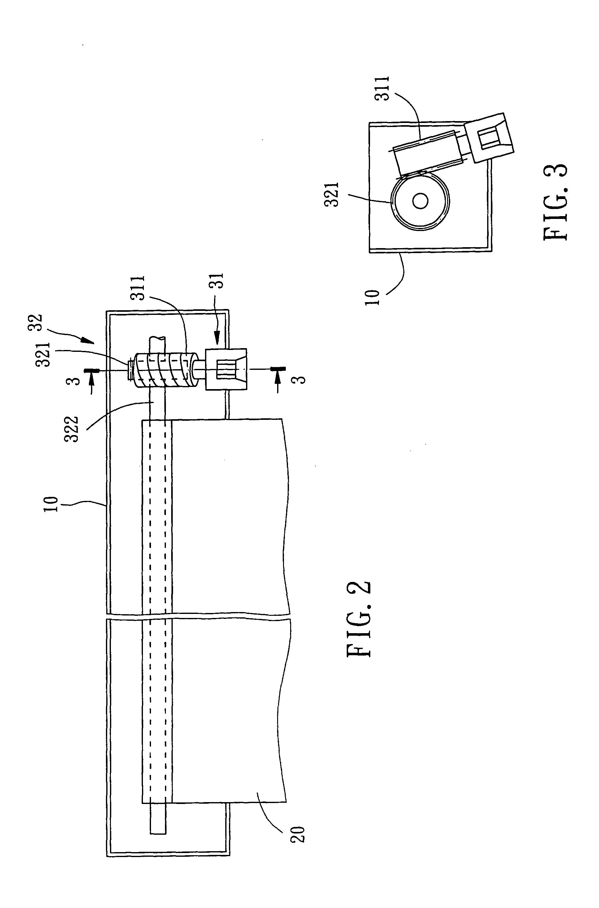
[0018] The linking mechanism 30 is a mechanical mechanism without power source installed in the headrail 10, comprising a power input device 31 and an actuator 32. The power input device 31 is rotatable by an external biasing force. The actuator 32 is directly (or indirectly) coupled to the blind body 20, and rotatable subject to the ...


PUM


Abstract

A window blind is constructed to include a headrail, a blind body suspended below the headrail, a linking mechanism mounted inside the headrail and having a power input device fastened pivotally with the headrail and an actuator rotatable with the power input device and connectable to the blind body, and a driving control mechanism. The driving control mechanism includes a suspension rod suspended from the headrail and a controller detachably coupled to the suspension rod for enabling the suspension rod to be driven by the controller to rotate the power input device and to further drive the actuator to move the blind body, causing the blind body to change the window shading status.

Description

BACKGROUND OF THE INVENTION [0001] 1. Field of the Invention [0002] The present invention relates generally to a window blind and, more specifically, to a window blind having multiple driving modes. [0003] 2. Description of the Related Art [0004] Conventional window blinds include two types, one with the cord members exposed to the outside, the other with the cord members arranged in a hidden status. A window blind with exposed cord members is not safe in use because the exposed cord members are accessible to children, and an accident may happen when a child playing with the cord members for fun. Therefore, window blinds with exposed cord members are not popularly acceptable at the present time. [0005] Various window blinds with hidden cord members have been disclosed, and have appeared on the market. These window blinds with hidden cord members include manually operated type window blinds and motor-driven type window blinds. A manually operated type window blind uses the tension fo...

Claims


Application Information

Patent Timeline
Patent Type & Authority Applications(United States)
IPC IPC(8): E06B9/74E06B9/76
CPCE06B9/76E06B9/74
Inventor NIEN, MING
Owner NIEN MADE ENTERPRISE CO LTD
Learn More