
Bow stabilizer

Active Publication Date: 2005-01-20
BEE STINGER LLC
View PDF9 Cites 6 Cited by
  • Summary
  • Abstract
  • Description
  • Claims
  • Application Information

AI Technical Summary

Benefits of technology

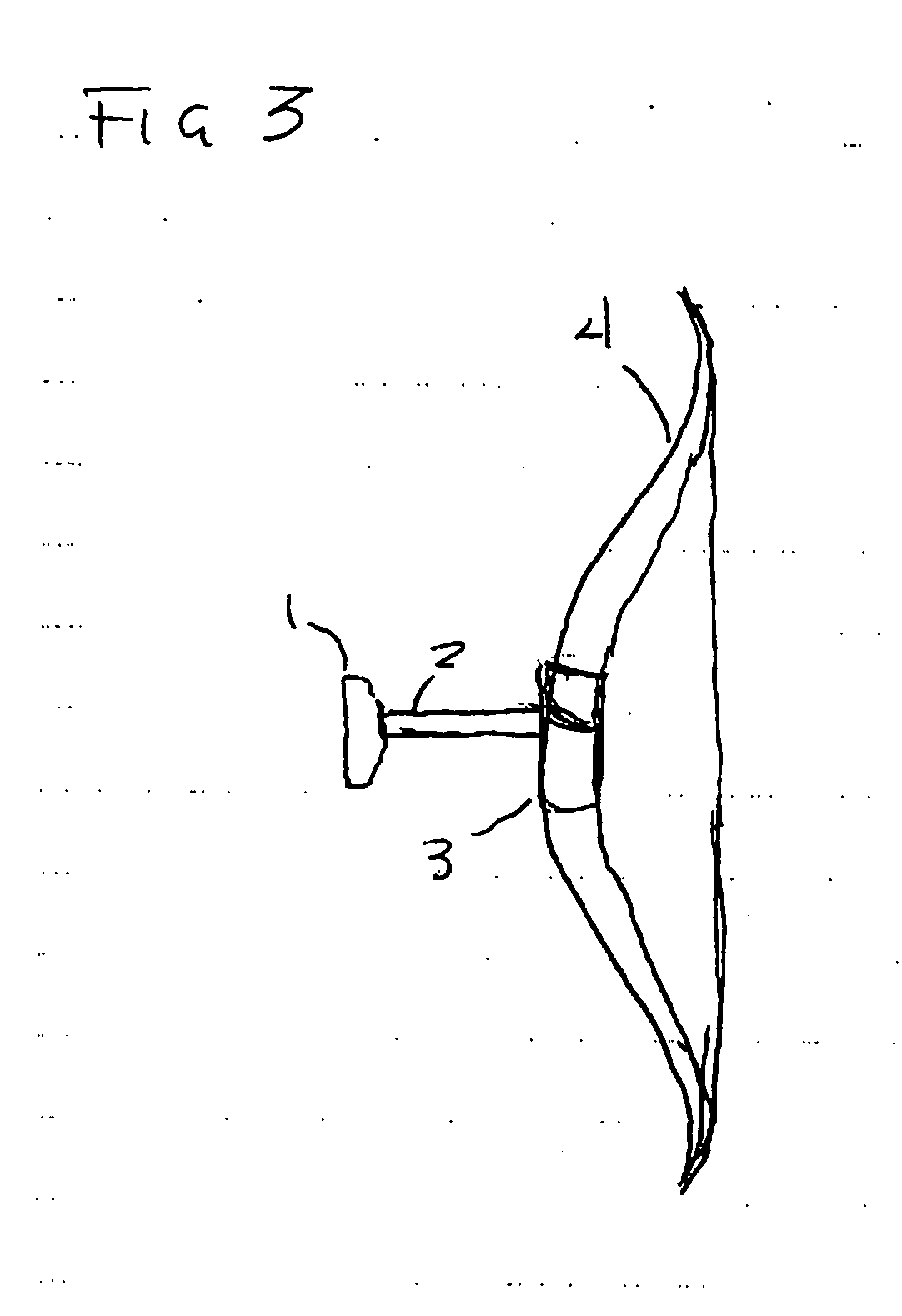
[0009] Accordingly, in one embodiment of the present invention a stabilizing device for an archery bow provides the maximum inertia for a given mass, thereby stabilizing the bow against motions imparted by the archer or any other external forces.

Problems solved by technology

A major source of inaccuracy when shooting an arrow with a bow is the instability of the bow position as it is held by the archer.
Practical considerations such as ease of use and transportation or the rules of competitive archery limit the allowable length of the stabilizing device.

Method used


Image

  • Bow stabilizer
  • Bow stabilizer
  • Bow stabilizer

Examples


Embodiment Construction

)

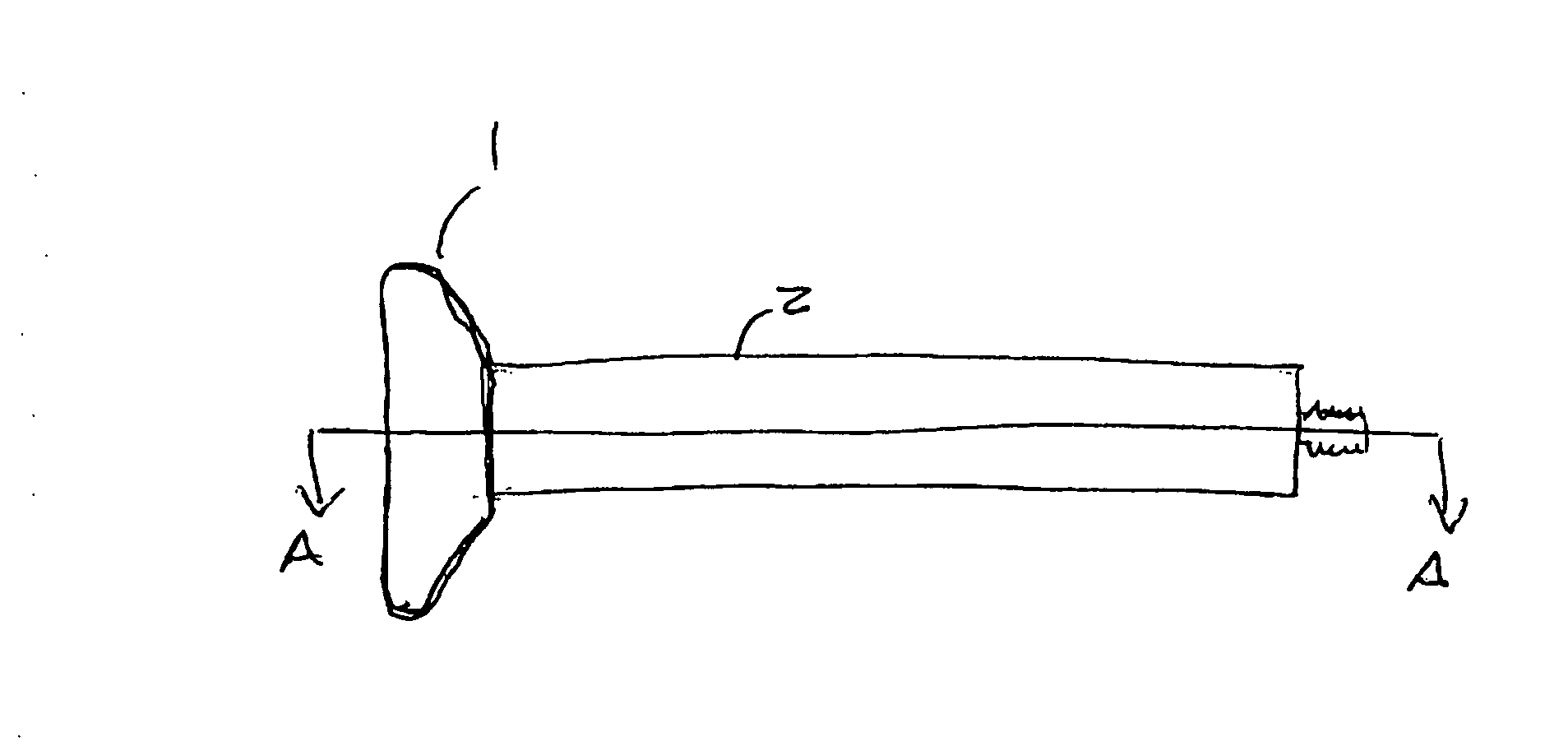
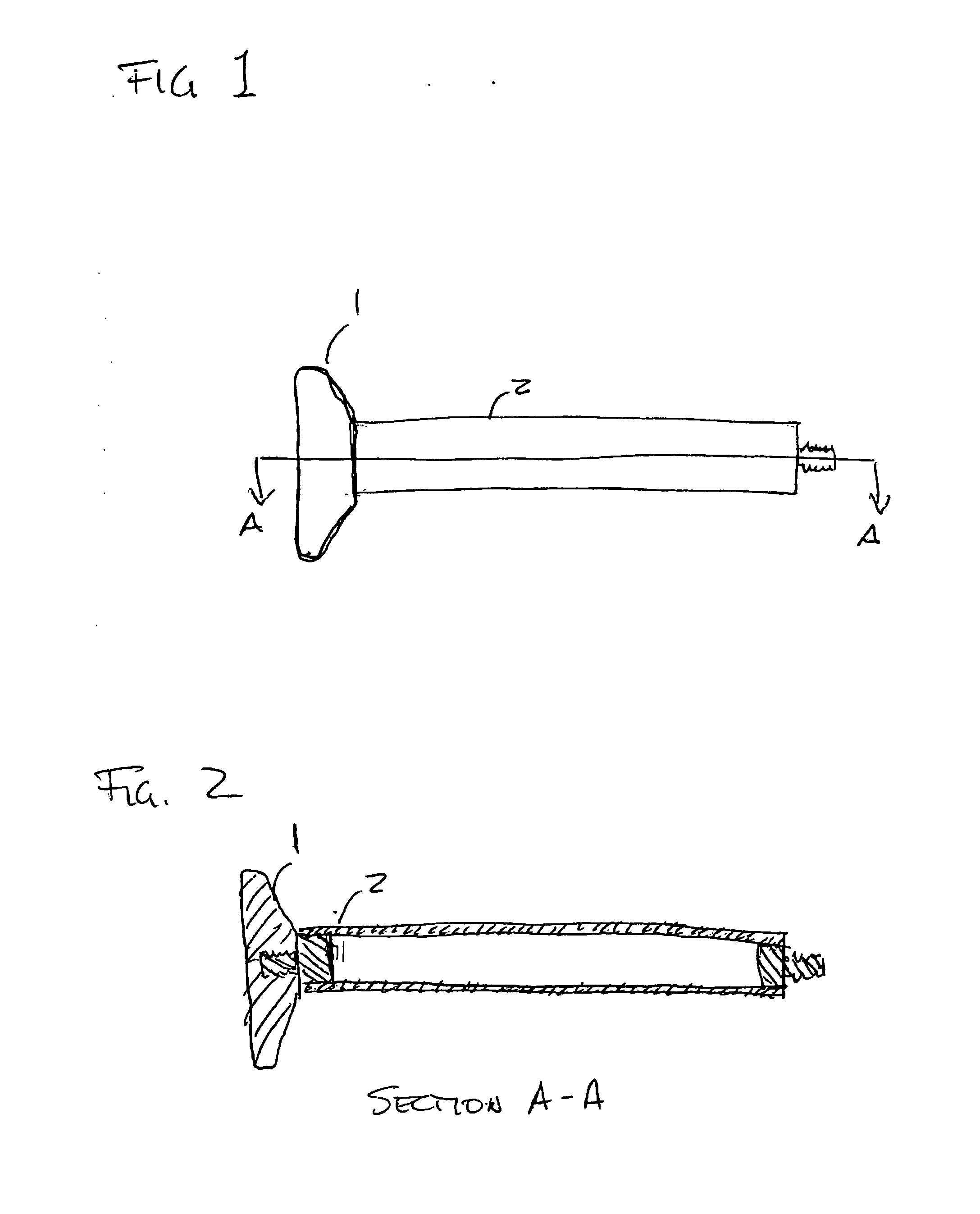
[0022]FIG. 1 shows a preferred embodiment of the invention in which stabilizing weight 1 is attached to supporting rod 2. The stabilizing mass is shown with a shape that tends to concentrate its mass at the end of the supporting rod. As shown in FIG. 1, this means that the dimension of the mass in the direction along the length of the supporting rod is short compared to a dimension of the mass transverse to that length. In this specific case, the mass is shown as a disk whose dimension along the length of the rod, or thickness, is approximately one fifth its dimension transverse to the rod length, or diameter. Weight 1 may be attached to supporting rod 2 using a variety of common methods. These methods include the use of a threaded connection with an internal thread in weight 1 and an external thread on the distal end of supporting rod 2, a screw connection with a screw passing through weight 1 and threading into supporting rod 2, and other methods such as welding or bonding.

[0023...


PUM


Abstract

In one embodiment, a bow stabilizer for an archery bow has an elongated member having a near end for attachment to an archery bow and a distal end, the elongated member having a length L, and a weight attached to the elongated member proximate the distal end. The center of gravity of the elongated member and weight is located within 25 percent of length L from the distal end of the elongated member. In another embodiment, the stabilizer has an elongated member having a near end for attachment to an archery bow, a distal end, and a weight attached to the elongated member proximate the distal end. The natural frequency of the first bending mode of the elongated member and weight is at least 20 Hz. In a further embodiment, the stabilizer has an elongated member having a near end for attachment to an archery bow and a distal end, and a weight attached to the elongated member proximate the distal end. The weight has a first mass M1 which is at least 1.2 times a second mass M2 of the elongated member.

Description

BACKGROUND OF THE INVENTION [0001] A major source of inaccuracy when shooting an arrow with a bow is the instability of the bow position as it is held by the archer. In the prior art, there are numerous examples of devices intended to mitigate this instability. Examples include U.S. Pat. No. 3,196,860(Hoyt), U.S. Pat. No. 3,752,142(Morita), U.S. Pat. No. 3,804,072(Izuta), U.S. Pat. No. 4,054,121(Hoyt), and U.S. Pat. No. 4,982,719(Haggard). As a specific case, Hoyt (U.S. Pat. No. 3,196,860) describes a device having rods with weighting elements with the rods mounted in various orientations on the bow. Morita, Izuta, and Hoyt (U.S. Pat. No. 4,054,121) further describe similar devices with various orientations of the rods and weights. There are also devices similar to that described by Haggard which incorporate a flexible element. Such flexible elements ostensibly serve the purpose of absorbing vibrations. [0002] The present inventor has recognized many fundamental issues that must be ...

Claims


Application Information

Patent Timeline
IPC IPC(8): F41B5/20
CPCF41B5/1426
Inventor SANDBERG, BLAIR A.
Owner BEE STINGER LLC
Learn More