
Bump stop device

Active Publication Date: 2005-01-13
AB SKF
View PDF40 Cites 56 Cited by
  • Summary
  • Abstract
  • Description
  • Claims
  • Application Information

AI Technical Summary

Benefits of technology

[0012] Finally, a suspension bump stop rolling bearing with a high degree of imperviousness that may easily be assembled, cannot be dismantled and is cheap to fabricate is also described.
[0024] This fabrication method can easily be applied to a suspension bump stop device: the races are secured with lower and upper annular cups, rolling elements are placed between the races to form a suspension bump stop thrust bearing, the bearing is placed between a cup of a spring and an elastic support block secured to the vehicle chassis, the upper cap forming an interface between said upper race and the elastic block with which it is placed in contact, the lower cap forming an interface between the lower race and the cup with which it is placed in contact, each cap including a thick portion and a thin portion, the thin portion of one cap being situated axially opposite the thick portion of the other cap, the lower and upper races bearing against the thick portions of the lower and upper caps thereby forming an angular contact rolling bearing. The races easily enable the fabrication of an angular contact rolling bearing that may take axial and radial loads.

Problems solved by technology

However, the bearing seal thus obtained is not satisfactory.
Pollution of the bearing by external elements may, in the long run, adversely affect the operation of the bearing.

Method used


Image

  • Bump stop device
  • Bump stop device
  • Bump stop device

Examples


Embodiment Construction

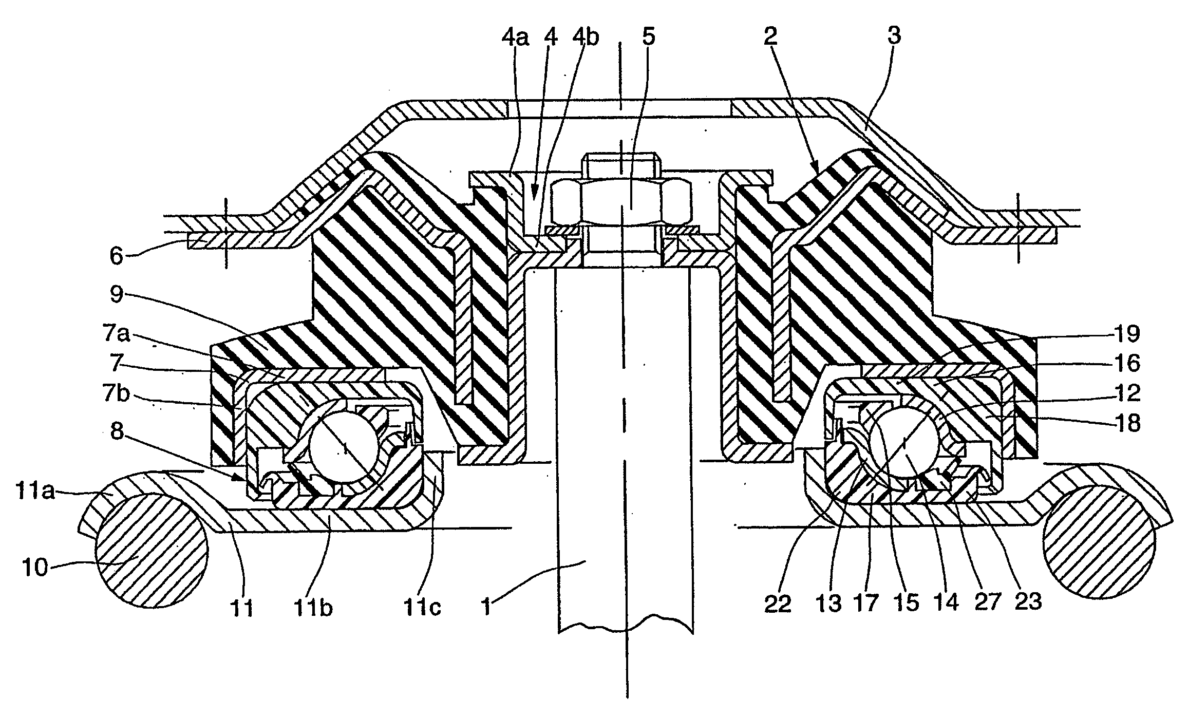
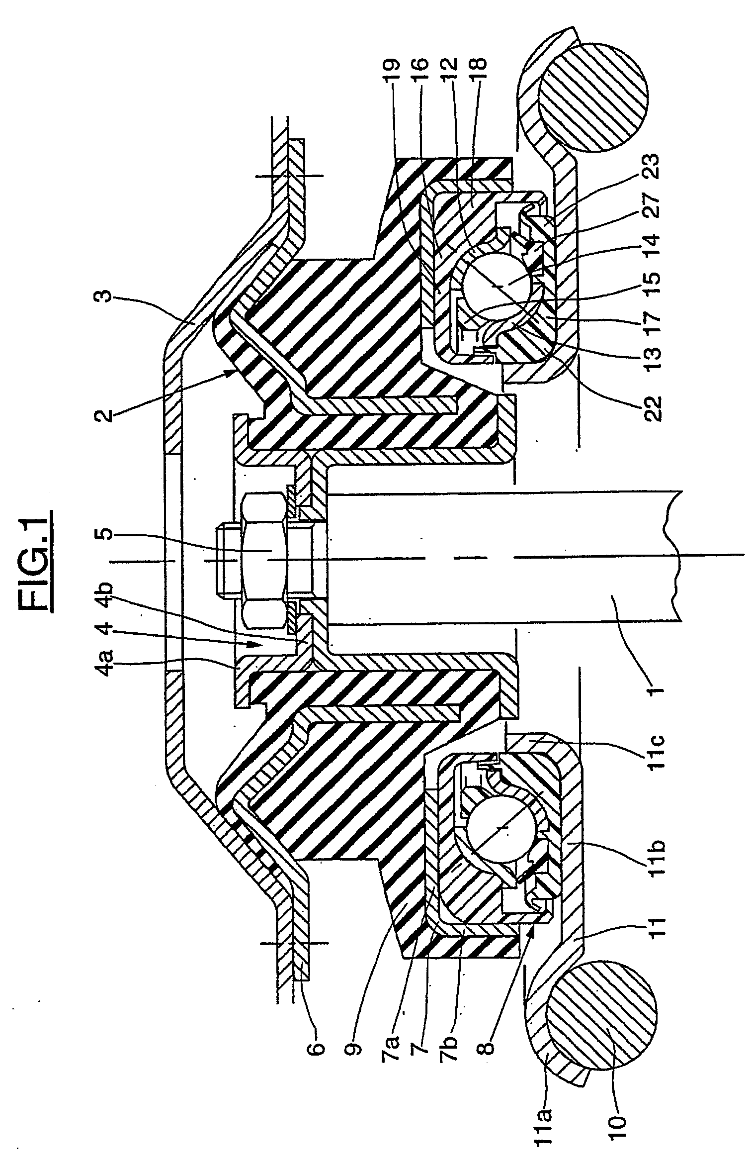
[0031] In FIG. 1, a damper includes a cylinder, not shown, in which a piston can slide whose rod 1 is linked at its top end to an elastic support block 2 which bears against an element of the chassis 3 forming a seat while being secured to the latter. The elastic support block 2 includes an internal annular link element 4 made up of two portions 4a and 4b onto which the end of the damper piston rod 1 is mounted by means of a nut 5, an annular external link element 6 used for securing to the chassis 3, an annular upper cup 7 acting as a seat for the bump stop rolling bearing 8, a rubber block 9 bonded to the surface of these three parts and forming a link between the latter with filtration of vibrations.

[0032] The external linking element 6 is attached to the chassis 3, for example by screwing or bolting. The upper cup 7 is placed axially on the internal linking element 4, but is of greater diameter. Also shown is the suspension spring 10 the top of which bears against a lower annul...


PUM


Abstract

The invention concerns a vehicle bump stop comprising a rolling bearing forming a stop element (8), a support spring retainer (11), and an elastic support block (2), the rolling bearing including an upper race (12) arranged in an annular upper cap (16) forming a contact surface between said upper race (12) and the elastic block (2), a lower race (13). The device comprises an annular lower cap (17) forming a contact surface between the lower race (13) and the support spring retainer (11). The caps (16, 17) comprise each a thick portion (18, 22) and a thin portion (19, 23), the thin portion (19, 23) being located axially opposite the thick portion (22, 18) of the other cap, the lower (13) and upper (12) races being urged to be pressed on the thick portions (22, 18) of the lower (17) and upper (16) caps forming a rolling bearing with oblique contact.

Description

BACKGROUND OF THE INVENTION [0001] 1. Field of the Invention [0002] The present invention relates to the field of suspension bump stops used, in particular, in motor vehicles on the telescopic suspension struts of the steered wheels. [0003] 2. Description of the Relevant Art [0004] A suspension bump stop usually includes an upper race and a lower race between which are placed rolling elements, in the form of balls or rollers. [0005] A suspension bump stop is usually placed at the top of the suspension strut between a lower metal cup that also acts as a seat for a suspension spring, and an upper element secured to the vehicle body. The spring of the suspension device is installed around the rod of the damper piston whose end is secured to an elastic support block. The suspension bump stop bearing allows a rotating motion between the spring cup, able to rotate, and the elastic support block that is attached to the vehicle body. The relative angular movement between the spring cup and ...

Claims


Application Information

Patent Timeline
IPC IPC(8): B60G15/06B60G13/08F16C19/16F16C27/06F16C33/64F16C33/76F16C33/78F16C33/80F16C35/073F16C35/077F16F9/32
CPCB21D53/10B60G15/068B60G2202/312B60G2204/128B60G2204/418B60G2204/4502F16C33/80F16C27/066F16C33/64F16C33/78F16C2326/05F16C33/761F16C19/163F16C19/10
Inventor BEGHINI, ERICGORETTE, RAPHAELHOUDAYER, CHRISTOPHE
Owner AB SKF
Learn More