
Display stand with foldable self erecting supporting base

a self-erecting, display stand technology, applied in the field of display stands, can solve the problems of manual and painstakingly unfolding and erection of the display stand base at the display location, difficulty in self-erecting operation of the support of such construction, and difficulty in separating the two

Active Publication Date: 2005-01-13
POPTECH
View PDF2 Cites 14 Cited by
  • Summary
  • Abstract
  • Description
  • Claims
  • Application Information

AI Technical Summary

Benefits of technology

[0004] It is a principal object of the present invention to provide a display stand having a self erecting base in which the self erecting mechanism is effective in unfolding and erecting the base.
[0006] It is another object of the present invention to provide a display stand in which the display tray may be removably attached to the base so that the base may be easily separated from the tray for folding and packing it within the tray thereafter.

Problems solved by technology

Such display stands are shown in U.S. Pat. No. 2,066,844 to H. E. Lynch; U.S. Pat. No. 3,300,166 to W. P. Wojciechowski; U.S. Pat. No. 4,582,283, to P. Schmitt; and U.S. Pat. No. 4,813,536 to W. T. Willis. The main drawback of such display stands is that the base must be manually and painstakingly unfolded and erected at the merchandise display location.
This process is often rather awkward and frustrating to carry out due to the stiffness of the cardboard material which renders the base difficult to unfold and to erect.
Such display stand is shown in U.S. Pat. No. 4,726,476 to J. S. Smith. However, the self erecting operation of the base of such construction is problematic because the folded base tends to retain its collapsed shape permanently and it could not be unfolded by its self erecting mechanism.
This problem is particularly severe when the folded base is compressed for a relatively lengthy period of time by the weight of the merchandise packaged in the tray.

Method used


Image

  • Display stand with foldable self erecting supporting base
  • Display stand with foldable self erecting supporting base
  • Display stand with foldable self erecting supporting base

Examples


Embodiment Construction

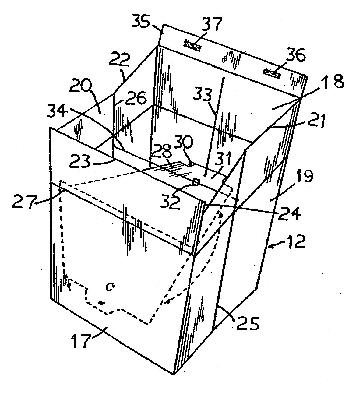
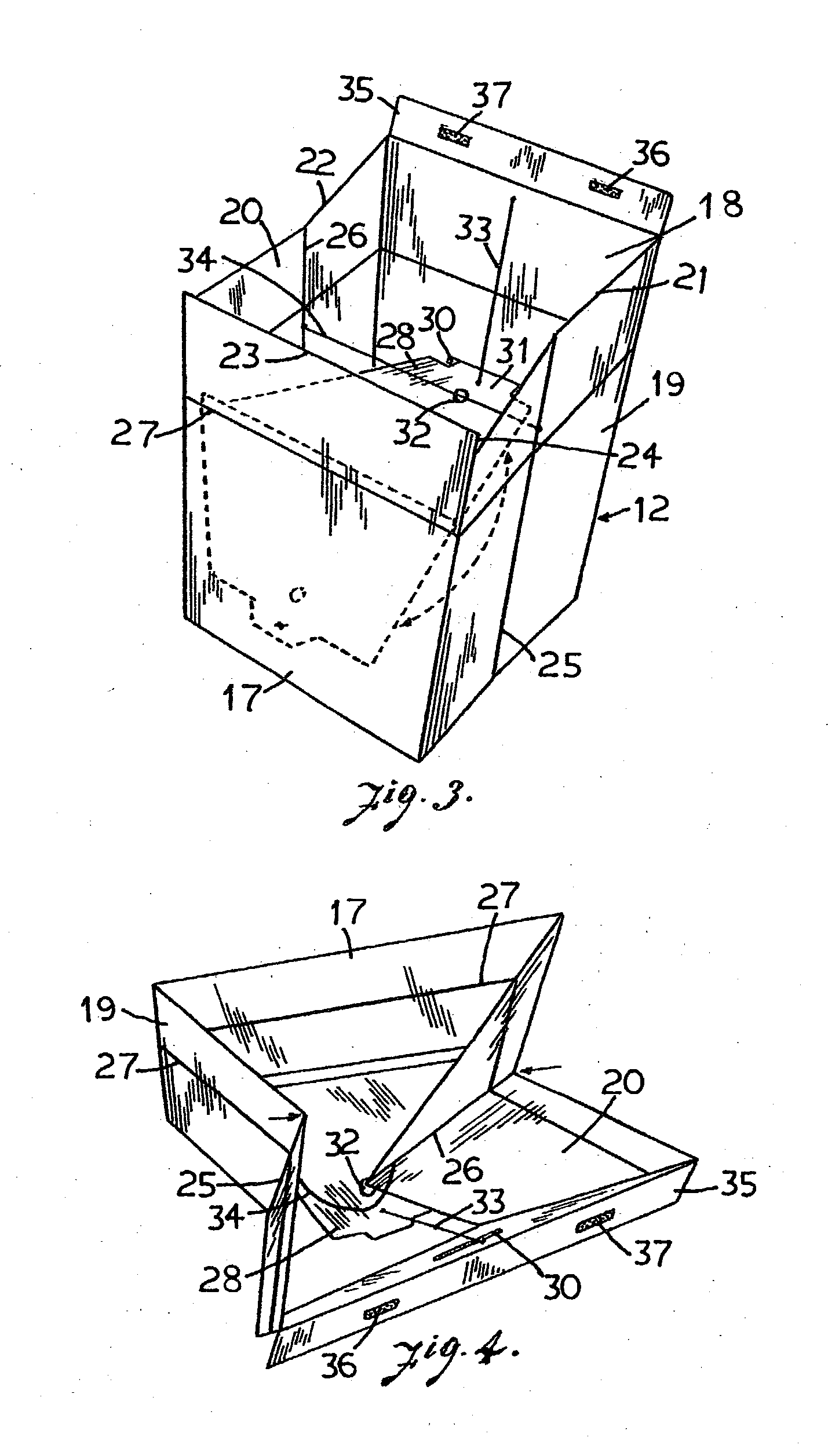
[0014] With reference to the drawings, the display stand 10 of the present invention has a display tray 11 disposed on top of a substantially rectangular base 12. The tray 11 may be used for packing the merchandise for transportation, shipping, and for displaying the merchandise when the stand is erected. The tray 11 is generally rectangular in shape and is provided with two handle openings 13 and 14 on two opposite side walls 15 and 16 respectively to facilitate its handling.

[0015] The base 12 has a generally rectangular horizontal cross sectional shape and it may be slightly larger at the bottom and tapering upwards to a smaller top end so as to provide better stability when the base is standing on a supporting surface. The front panel 17 is shorter in height than the rear panel 18, such that when the tray 11 is placed on the stand it may be in a slanted position to provide a better view of the merchandise displayed therein. The two side panels 19 and 20 have sloping top edges 21...


PUM


Abstract

A display stand has supporting base which is self erecting by a pivotal board located within the base. The pivotal board is biassed by an elastic cord and is pivotable between a horizontal position transverse to the base and a vertical downward position at which it is juxtaposed to the front panel of the base. The pivotal board is engageable with a horizontal slot opening formed in the rear panel of the base for maintaining the base in the erected condition. The side panels of the base are also foldable inwards along two vertical fold lines formed in the middle therein. A second elastic cord is connected between these fold lines so that it would pull the side panels to fold inwards at the vertical fold lines when the pivotal board is pulled downwards to disengage from the horizontal slot opening. A display tray is disposable in a forward sloping position on the base and the base in the collapsed folded condition may be placed within the tray for shipping, transporting, or storage.

Description

FIELD OF THE INVENTION [0001] This invention relates to a display stand having a tray and a self erecting supporting base which is also foldable in a collapsed condition for packing with merchandise in the tray for shipping, transporting and storage. BACKGROUND OF THE INVENTION [0002] Display stands made of cardboard or corrugated board material are commonly used for displaying merchandise. Such display stands have either a flat top or a tray for displaying the merchandise. The top is supported by a base which may be folded over or under the tray for storage or transportation. The base is often attached to or integrally formed with the tray such that the display stand is formed readily when the base is erected. Such display stands are shown in U.S. Pat. No. 2,066,844 to H. E. Lynch; U.S. Pat. No. 3,300,166 to W. P. Wojciechowski; U.S. Pat. No. 4,582,283, to P. Schmitt; and U.S. Pat. No. 4,813,536 to W. T. Willis. The main drawback of such display stands is that the base must be manu...

Claims


Application Information

Patent Timeline
IPC IPC(8): A47F5/11B65D5/36B65D5/52
CPCA47F5/114B65D2313/02B65D5/5206B65D5/3628
Inventor MOSS, GEOFFREY ALANMINISTER, DAVID BRIAN
Owner POPTECH
Learn More