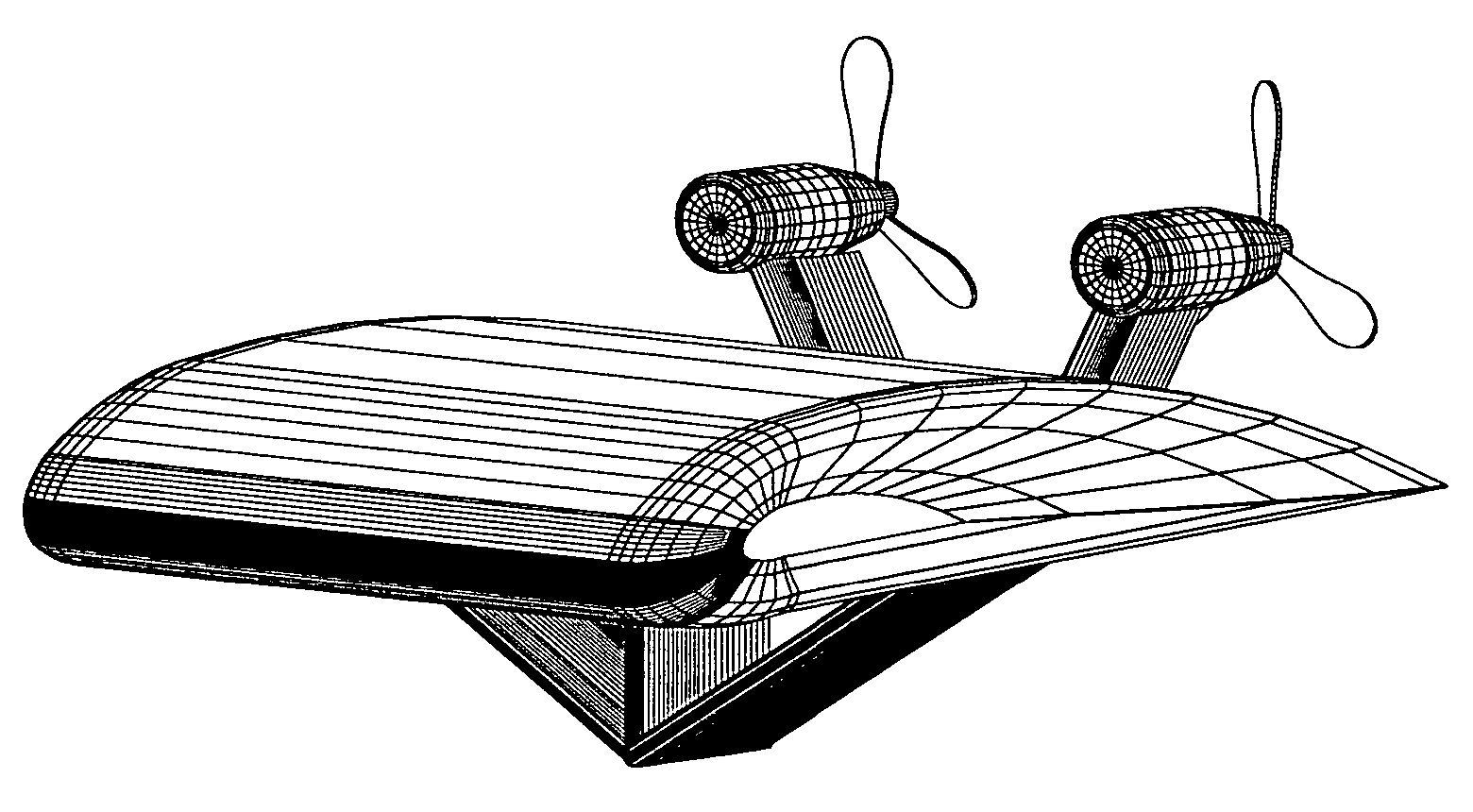
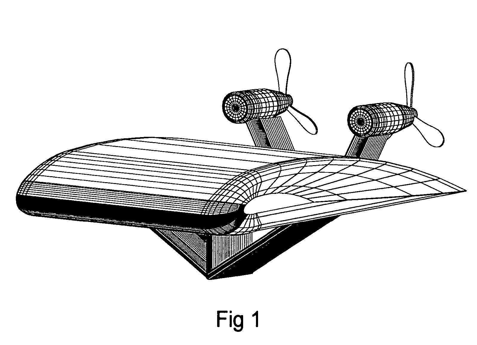
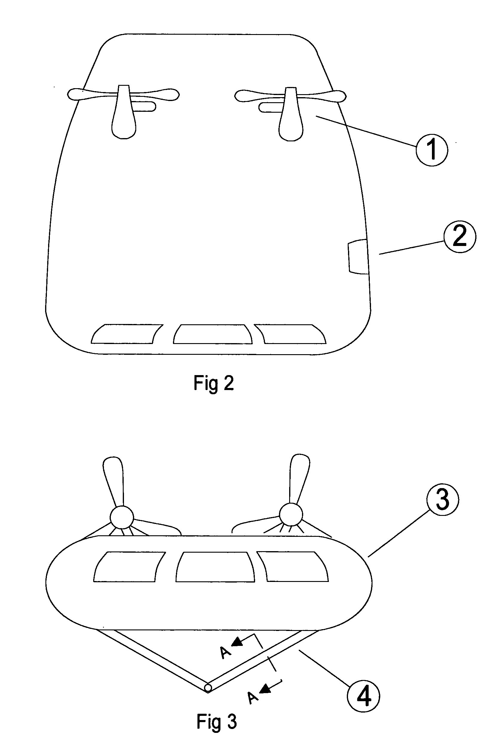
Passenger watercraft using three methods of lift; displacement, hydrofoil, and ground-effect (wing-in-ground) operating over water
a technology of watercraft and water cylinders, applied in special-purpose vessels, vessel construction, transportation and packaging, etc., can solve the problems of limiting the ability of watercraft to operate in very shallow water, affecting the safety of passengers, so as to achieve safe, convenient, and economical transportation over water
- Summary
- Abstract
- Description
- Claims
- Application Information
AI Technical Summary
Benefits of technology
Problems solved by technology
Method used
Image

Examples
Embodiment Construction
[0021] The hybrid hydrofoil vessel hull is constructed using standard reinforced fiberglass techniques, with reinforced frame for rigid attachment of engines and hydrofoil wing. A jointed double wing, V shaped, with a pivot in the center and at each end allow retraction and deployment of the wing. The adjustment of the foil is accomplished with a vertical sliding arm that extends downward for deployment and receeds into the cabin for retraction. When fully retracted the wing is flush with the underside of the airfoil shaped cabin allowing a streamlined shape for very low drag.
[0022] Aircraft propellers are used of the “constant velocity” type with reversable thrust capability. Each motor and prop are individually controllable and are used for directional control, including reverse maneuvering at slow speeds. In addition, elevator surfaces are located at the rear of the vessel providing angle-of-attack trim at moderate and high speeds.
PUM
 Abstract
Description
Claims
Application Information
 - R&D
- Intellectual Property
- Life Sciences
- Materials
- Tech Scout
- Unparalleled Data Quality
- Higher Quality Content
- 60% Fewer Hallucinations
Browse by: Latest US Patents, China's latest patents, Technical Efficacy Thesaurus, Application Domain, Technology Topic, Popular Technical Reports.
© 2025 PatSnap. All rights reserved.Legal|Privacy policy|Modern Slavery Act Transparency Statement|Sitemap|About US| Contact US: help@patsnap.com