
Tire pressure gauge

a tire pressure gauge and tire pressure gauge technology, applied in the direction of tyre measurement, instruments, alarms, etc., can solve the problem of inconvenient spring replacement in the tire pressure gauge, and achieve the effect of maintaining the precision of the tire pressure gaug

Inactive Publication Date: 2005-01-13
HUANG TIEN TSAI
View PDF2 Cites 11 Cited by
  • Summary
  • Abstract
  • Description
  • Claims
  • Application Information

AI Technical Summary

Benefits of technology

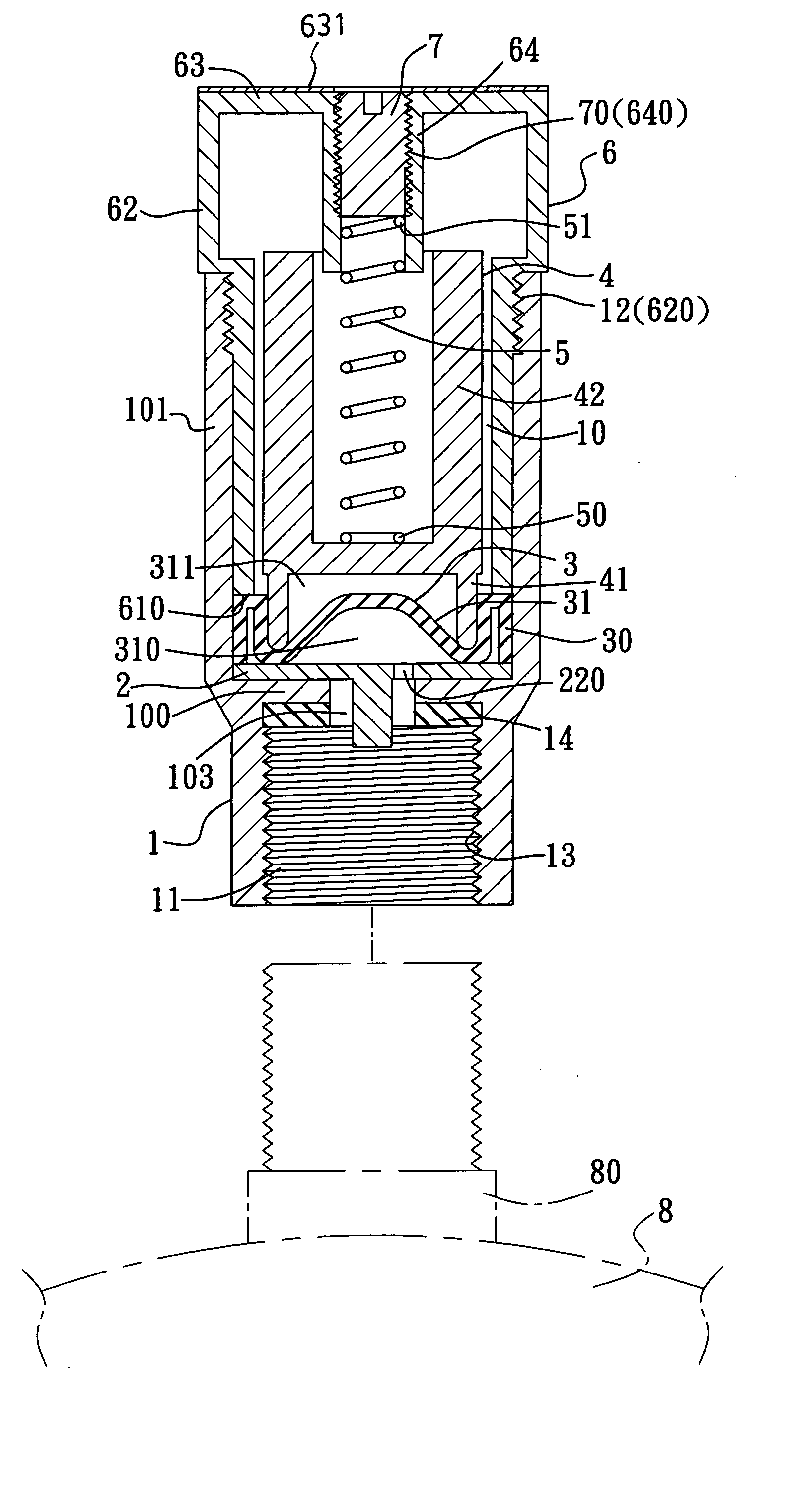
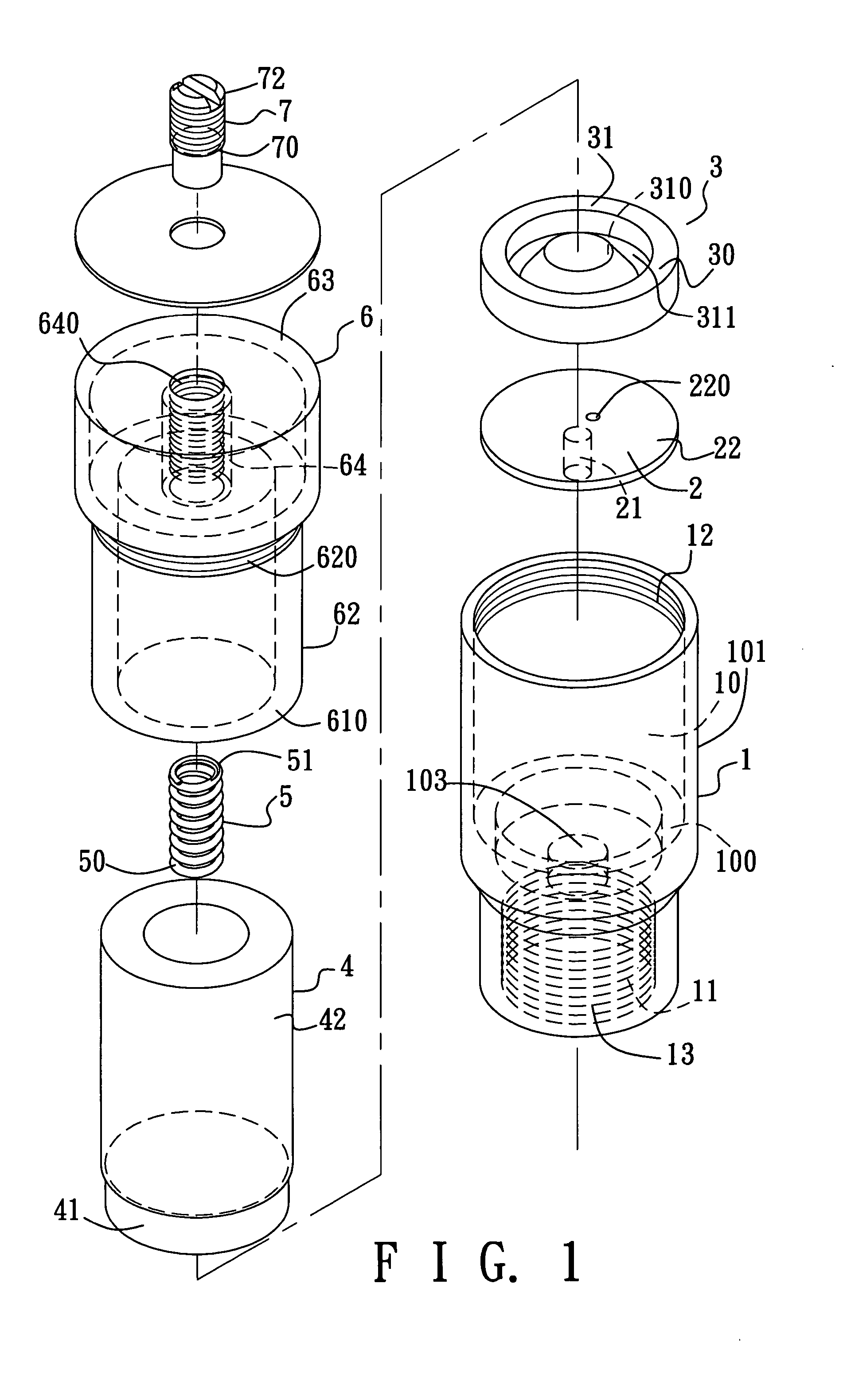
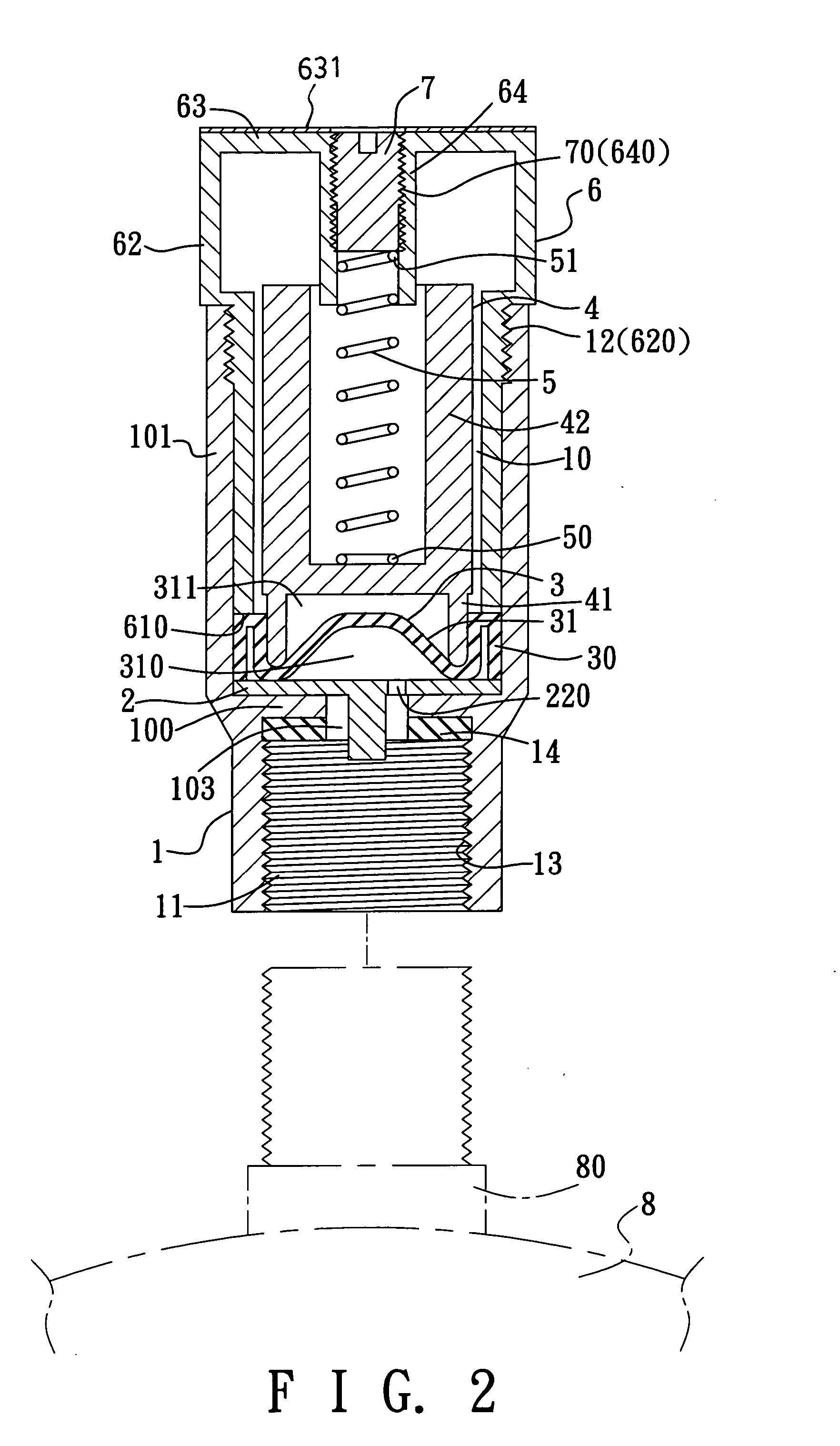
"The present invention provides a tire pressure gauge that allows for easy replacement of the spring and has correction means to maintain accuracy. The gauge includes a housing with an inner wall that divides the space into a receiving chamber and a coupling chamber for attaching to a tire nozzle. An air ventilating member is secured to the inner wall and includes a projection and a vent hole to allow air to enter the receiving chamber. A flexible diaphragm is placed in the receiving chamber to separate it into compressible and expandable regions, with the expandable region being connected to the opening through the vent hole. A pressure indicating member is positioned below the flexible diaphragm and is moved with its raised portion. An adjustable member is mounted in the mounting hole and is movable relative to the cap. A biasing member is positioned between the pressure indicating member and the adjustable member to bias it towards the air ventilating member."

Problems solved by technology

However, the adjustable extension member, which is not fastened to the plunger, may rotate with a slender pen element during adjustment of the adjustable extension member, thereby resulting in inconvenience.
However, replacement of the spring is not convenient in this tire pressure gauge.

Method used


Image

  • Tire pressure gauge
  • Tire pressure gauge
  • Tire pressure gauge

Examples


first embodiment

[0030] Referring to FIG. 4, the second preferred embodiment of a tire pressure gauge according to this invention is shown to be similar to the first embodiment, except that the adjustable member 7 has first and second portions 701,702 which are opposite to each other along the central axis and which are respectively proximate to the top wall 63 of the cap 6 and the lower portion 41 of the pressure indicating member 4. The first and second portions 701,702 respectively have yellow and red colors. As such, when the detected tire pressure is normal, the sleeve wall 42 of the pressure indicating member 4 will surround the first and second portions 701,702 completely. If the detected tire pressure is insufficient, the yellow first portion 701 and even the red second portion 702 will be visible through the barrel wall 62 of the cap 6, thereby warning the user of a decreased tire pressure.

second embodiment

[0031] Referring to FIG. 5, in the third preferred embodiment of this invention, an indicating sleeve 9 is further disposed to be sleeved on the tubular wall 64 of the cap 6, and has first and second portions 91,92 which are opposite to each other along the central axis and which are respectively proximate to the top wall 63 of the cap 6 and the lower portion 41 of the pressure indicating member 4. The first and second portions 91,92 respectively display yellow and red colors. The effect and function of this embodiment are substantially the same as-those in the

[0032] When it is desired to measure a higher tire pressure, the adjustable member 7 is removed from the mounting hole in the tubular wall 64 to permit replacement of the biasing member 5 with one having greater biasing force. This can be conducted in a convenient manner.

[0033] Referring to FIG. 6, for adjustment, the adjustable member 7 is turned to move towards the air ventilating member 2 along the central axis against the...


PUM


Abstract

A tire pressure gauge includes a tubular housing, an air ventilating member dividing the housing into receiving and coupling chambers, a flexible diaphragm disposed in the receiving chamber and having a raised portion which is movable in response to an air pressure introduced into the receiving chamber through the coupling chamber, which is coupled to a tire valve, so as to move a pressure indicating member relative to a cap in order to indicate the tire pressure condition, an adjustable member adjustably disposed in the cap, and a biasing member disposed between the pressure indicating member and the adjustable member so as to correct the position of the pressure indicating member.

Description

CROSS-REFERENCE TO RELATED APPLICATION [0001] This application claims priority of Taiwanese Application No. 092118875, filed on Jul. 10, 2003. BACKGROUND OF THE INVENTION [0002] 1. Field of the Invention [0003] This invention relates to a tire pressure gauge, more particularly to a tire pressure gauge having a replaceable biasing member so as to be suitable for use in measuring of tire pressures of different tires. [0004] 2. Description of the Related Art [0005] A conventional tire pressure gauge, such as those disclosed in U.S. Pat. Nos. 2,225,675, 5,886,254 and 6,525,655 B2, uses a flexible diaphragm to raise a piston in response to air pressure introduced into a casing from a detected tire such that the movement of the piston relative to an indicating member secured in the casing, can indicate the tire pressure of the tire. Since quality deviation often occurs in the manufacturing processes, means for correcting the initial position of the piston is needed for maintaining the pre...

Claims


Application Information

Patent Timeline
Patent Type & Authority Applications(United States)
IPC IPC(8): B60C23/00
CPCB60C23/0496
Inventor HUANG, TIEN-TSAI
Owner HUANG TIEN TSAI
Learn More