
Communications terminal

a terminal and communication technology, applied in the field of portable terminals, can solve the problems of inability to exchanging handwritten data nor image data in real time, inability to add characters and graphics for more detailed information, and inability to add handwritten data to a transferred image,

Active Publication Date: 2004-11-25
MAXELL HLDG LTD
View PDF5 Cites 8 Cited by
  • Summary
  • Abstract
  • Description
  • Claims
  • Application Information

AI Technical Summary

Benefits of technology

[0010] It is an object of the present invention to provide a user-friendly communications terminal having a small display screen such as, for example, a portable terminal capable of sharing an image with the other terminal, exchanging handwritten data with the other terminal, and displaying the exchanged handwritten data on the shared image in real time. Particularly if one terminal has an image shared with the other terminal and is to display a candidate for the next shared image such as an image taken by a camera during communication, displaying the candidate shared image on the current shared image makes the current shared image invisible, thereby causing an inconsistency in the displayed image between the terminal and the other terminal. In another case, the current shared image is erased and the terminal cannot return to the original shared image even after canceling the display or transmission of the shared candidate image, thereby causing a trouble in communication.

Problems solved by technology

For example, the technology in Literature 1, however, lacks in consideration in a display screen size of the terminal.
The technology in Literature 2 relates to a facsimile and therefore it is incapable of exchanging handwritten data nor image data in real time, more specifically, incapable of adding handwritten data to a transferred image nor adding characters and graphics for more detailed information.
Furthermore, the data is not intended for exchanging in real time and therefore it is incapable of correcting and changing the data.
Particularly if one terminal has an image shared with the other terminal and is to display a candidate for the next shared image such as an image taken by a camera during communication, displaying the candidate shared image on the current shared image makes the current shared image invisible, thereby causing an inconsistency in the displayed image between the terminal and the other terminal.
In another case, the current shared image is erased and the terminal cannot return to the original shared image even after canceling the display or transmission of the shared candidate image, thereby causing a trouble in communication.

Method used


Image

  • Communications terminal
  • Communications terminal
  • Communications terminal

Examples


first embodiment

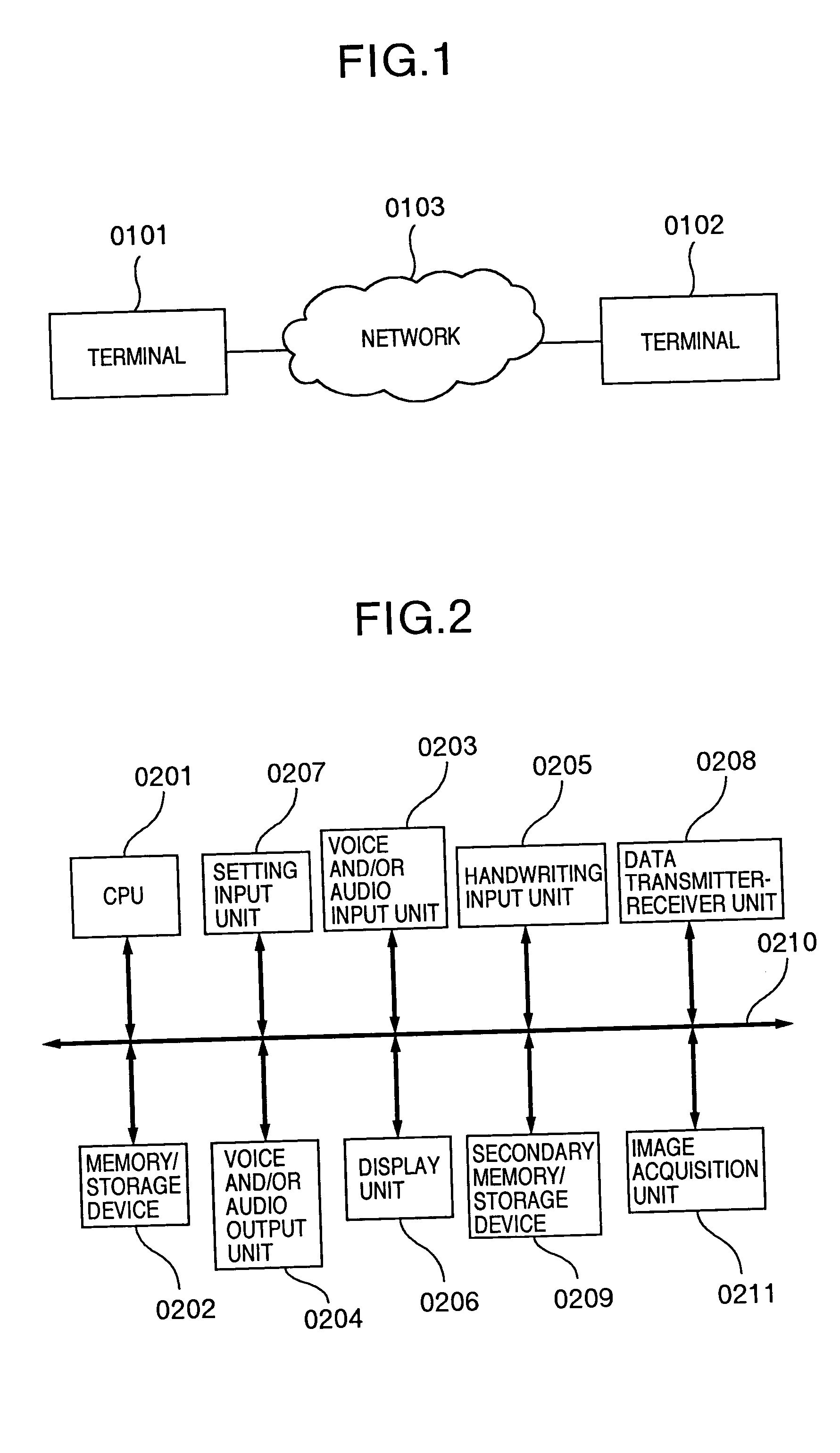
[0050] A first embodiment according to the present invention will now be described in detail hereinafter with reference to the accompanying drawings. Referring to FIG. 1, there is shown an example of a communications system structure using the terminal according to the embodiment of the present invention.

[0051] As shown in FIG. 1, the communications system using the terminal according to this embodiment comprises at least two terminals 0101 and 0102 and a network 0103; these terminals are capable of communicating with each other through the network 0103.

[0052] The network 0103 comprises an IP network typified by an Internet or a telephone network, ISDN, a PHS network, a cellular telephony network, or a network using a wireless LAN or the like.

[0053] The terminal 0101 and the terminal 0102 enable a user of the system to transmit and receive voice data, images, and handwritten data. They can be compact portable terminals such as, for example, a mobile telephone and a PDA or personal c...

second embodiment

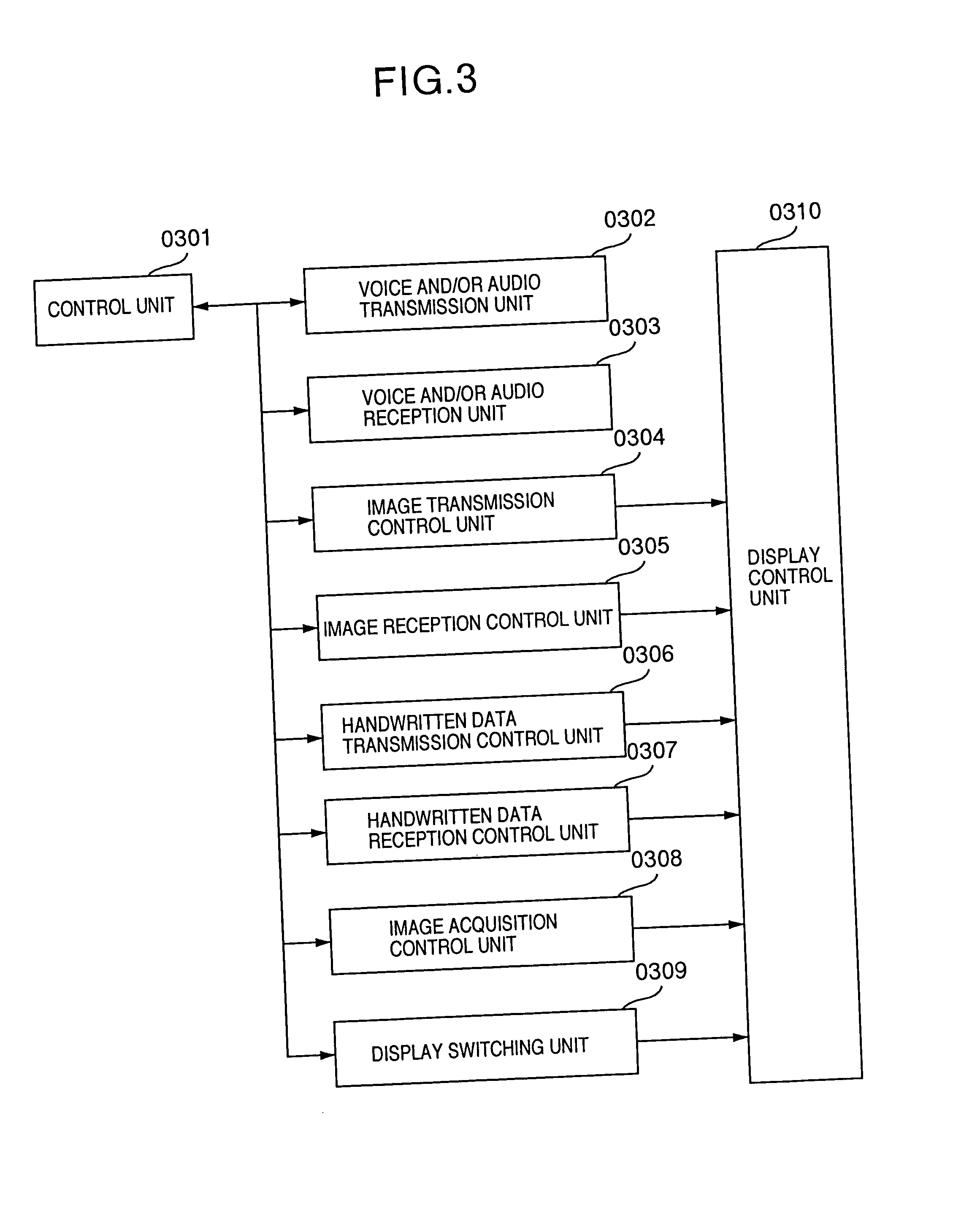
[0169] As shown in FIG. 18, an image acquisition control unit 0308 acquires image data from an image acquisition unit 0211 (step 1801) and sets it as a shared candidate image with the other terminal in communication (step 1802). It is achieved by acquiring the image data from the image acquisition unit 0211 and expanding it in a shared candidate image area on a memory / storage device 0202 and a secondary memory / storage device 0209.

[0170] Subsequently, the image acquisition control unit 0308 generates a reduced image of the shared candidate image set in the step 1802 (step 1803). The generated reduced image is preferably expanded in a reduced image area on the memory / storage device 0202 or the secondary memory / storage device 0209.

[0171] Subsequently, the image acquisition control unit 0308 sets on a small screen display so that the reduced image generated in the step 1803 is displayed in an image and handwritten data display area 0404 by means of a display control unit 0310 described...

third embodiment

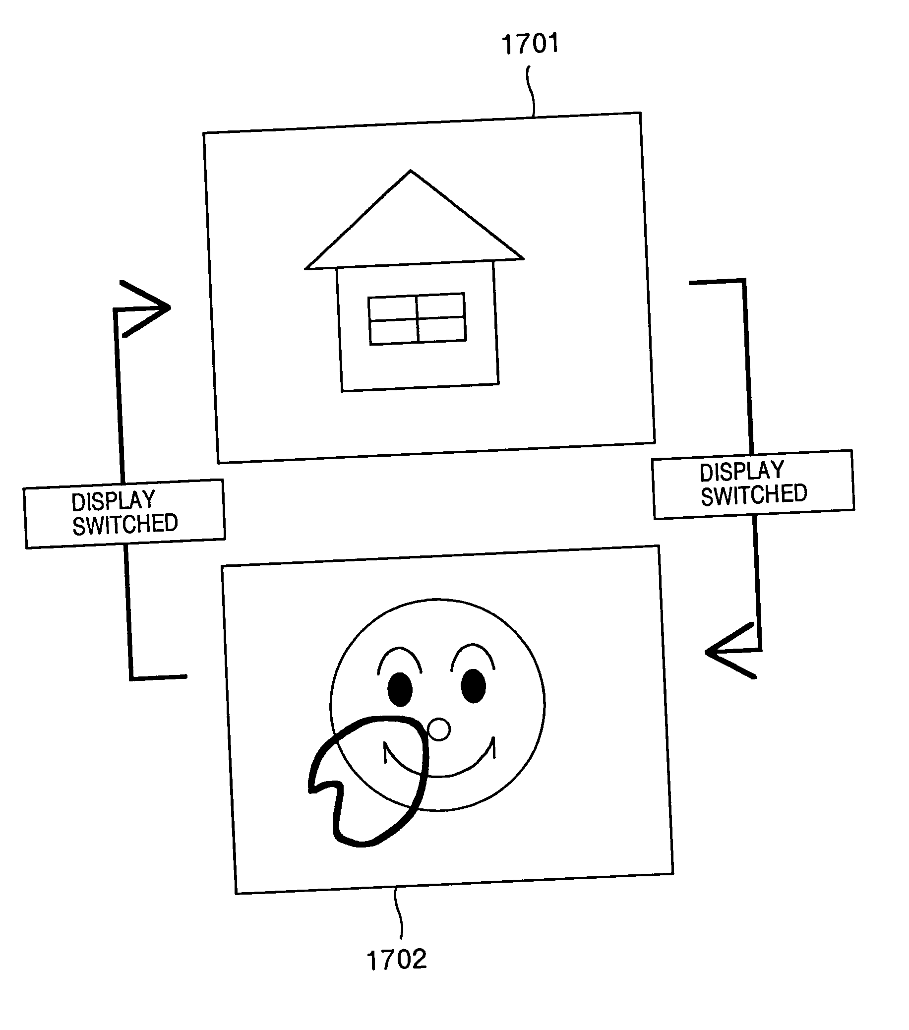
[0210] As shown in FIG. 31, the display switching unit 0309 first determines whether the shared candidate image display is ON (step 3101). If it determines that the shared candidate image display is ON, it sets on the small screen display, sets on the shared display, and sets off the shared candidate image display (step 3102). Thereafter, it starts a display control unit 0310 described later (step 3103) so that a reduced image of the shared candidate image is displayed in the image and handwritten data display area 0404 by means of the display control unit 0310 and then ends the processing of the display switching unit 0309.

[0211] On the other hand, unless the display switching unit 0309 determines that the shared candidate image display is ON in the step 3101, it further determines whether the small screen display is ON (step 3104). If it determines that the small screen display is ON, it sets off the small screen display, sets off the shared candidate image display, and sets on t...


PUM


Abstract

A terminal acquires and manages a shared candidate image to be a candidate for the next image shared with the other terminal, transmits or receives the image, and transmits or receives an image generated by superimposing handwritten data to be shared on a shared image. It switches an image display between the shared candidate image and an image to be displayed in such a way as to be triggered by a reception of a new shared image.

Description

[0001] 1. Field of the Invention[0002] The present invention relates to a portable terminal communicating with the other terminal by sharing images and handwritten data.[0003] 2. Description of the Related Art[0004] By way of examples of a communications system capable of exchanging image data such as a still image and handwritten data, there have been disclosed "the telewriting device" in JP-A-6-284241 (Literature 1) and the video conference system and the multifunctional facsimile described regarding "the audio visual communication apparatus" in JP-A-2002-330244 (Literature 2).[0005] The telewriting device is capable of writing a graphic or a text by means of a pointing device on a screen of a terminal fixed to a network such as a telephone line or an Ethernet.TM. and delivering the image written into the individual terminal between terminals to display the same image on the terminals.[0006] The multifunctional facsimile is capable of storing a handwritten message acquired by a sc...

Claims


Application Information

Patent Timeline
Patent Type & Authority Applications(United States)
IPC IPC(8): G06F13/00G06F3/00G06F3/048G06F3/0484G06F15/00G09G5/00H04L29/06H04M1/725H04N1/00H04N7/14H04N7/15
CPCG09G2340/145H04L29/06H04N2201/3245H04N2201/3273H04N2201/3278H04L67/38H04L9/40H04L67/131H04N7/14
Inventor HIROI, KAZUSHIGEHARA, TSUTOMUHANAOKA, SEISHIUMEMURA, MASAYASHIGEMATSU, KAZUO
Owner MAXELL HLDG LTD
Learn More