
Articulated wrench

Active Publication Date: 2004-11-25
DANAHER TOOL
View PDF14 Cites 9 Cited by
  • Summary
  • Abstract
  • Description
  • Claims
  • Application Information

AI Technical Summary

Benefits of technology

[0012] It is another objective of this invention to provide an articulated wrench implementing a flexed spring disc that does not need to enlarge the indent fro receiving the spring disc that guarantees lasting resilience and eliminates elastic fatigue.

Problems solved by technology

When the screw is subjected to forces, because most of the force is applied towards a top of the screw head, the screw head may be easily fractured.
However, the increment in the screw sizes results in enlargement of the cavity formed on the wrench body for receiving the screw, and thus reduces wall thickness of the wrench boy, thereby reducing the wrench strength.
However, the increment in the wall thickness results in increment in the overall thickness of the wrench, thereby reducing the flexibility and mobility of the wrench, or causing operation failure in a compact space.
However, elastic fatigue due to prolonged usage may cause reduction in the retaining force.
To eliminate such problems, the known measure of increasing the spring sizes results in enlargement of the indent formed on the box end of the wrench body for receiving the spring, and thus reduces the strength of the box end and causes difficulty in assembly.
Furthermore, the excessive resilience of the increase spring size may also cause difficulty and inconvenience in rotating the box end in the early stage of the application of the articulated wrench.

Method used


Image

  • Articulated wrench
  • Articulated wrench
  • Articulated wrench

Examples


Embodiment Construction

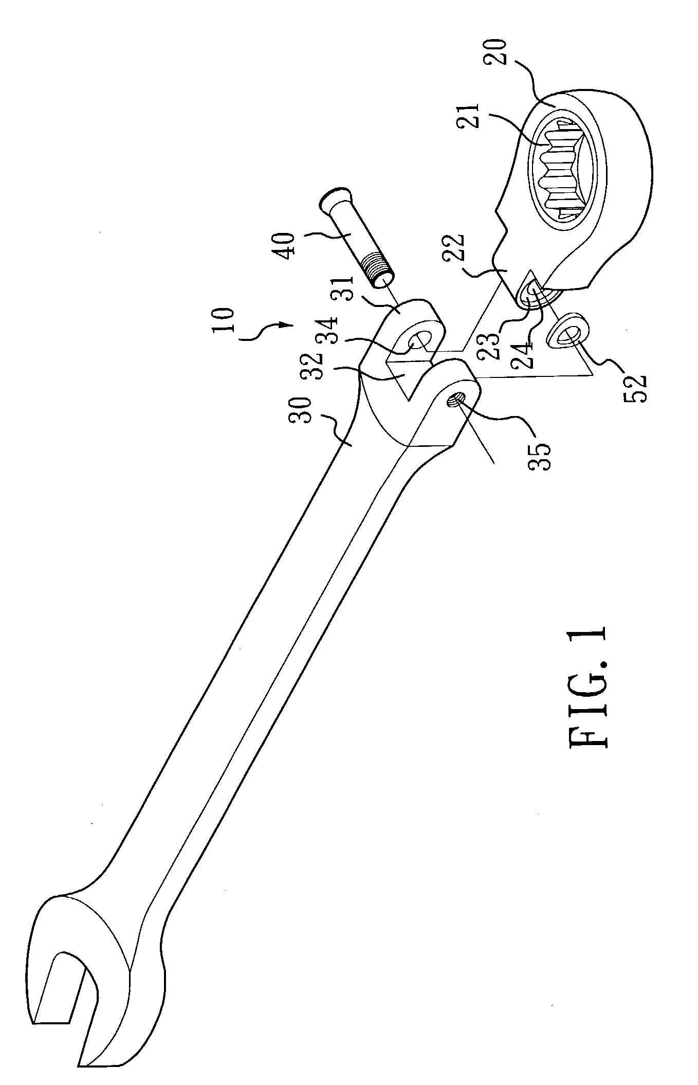
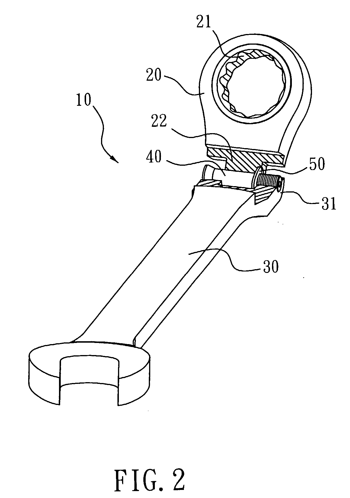
[0027] FIG. 1 illustrates an exploded view of an articulated wrench 10 of this invention. FIG. 2 illustrates an assembled view of the articulated wrench 10 of this invention, where part of the joint is removed.

[0028] The articulated wrench 10 of this invention comprises: a box end 20, a handle 30, a fastening device (a screw 40 in this invention) and a flexed spring disc.

[0029] The box end 20 includes two major surfaces and a peripheral surface defined between the two major surfaces. The handle 30 is of a flat, elongated configuration and includes two major surfaces and a peripheral surface defined between the two major surfaces.

[0030] The box end 20 is formed thereon with an opening penetrating the two major surfaces of the box end 20 for receiving a ratchet ring 21. The box end 20 is formed at an end thereof with at least one box knuckle 22. The box knuckle 22 is formed with an indent 23 at a side thereof and a through hole 24 penetrating the box knuckle 22 sideway and being subst...


PUM


Abstract

This invention provides an articulated wrench, comprising: a box end; a handle; a fastening device passing through the through holes of the box end and handle; and a flexed spring disc. The fastening device has a head and a shank, wherein the head gradually expands outwards from the shank to form a flared angle having a tapering angle less than 45°. The flexed spring disc is provided in the indent of the box end and flexed along a diameter thereof to form a curvature.

Description

CROSS-REFERENCES TO RELATED APPLICATIONS[0001] Not Applicable[0002] Not ApplicableDESCRIPTION[0003] 1. Field of Invention[0004] This invention is related to an articulated wrench, particularly to one implementing an improved head and a flexed spring disc.[0005] 2. Background of Invention[0006] As shown in FIGS. 5 and 6, conventional articulated wrenches mostly adopt a flat head screw or an oval head screw as well as a spring or a spring washer to construct the wrench joint to allow pivotal connection between a box end and a handle of the wrench.[0007] However, in operating such conventional articulated wrenches that implement the flat head screw, the screw head only sustains a vertical force component (Fv) without any horizontal force component (see FIGS. 5(a) and 5(b). For conventional articulated wrenches that implement the oval head screw, the vertical force component (Fv) sustained by the screw head is greater than the horizontal force component (Fh) (see FIGS. 6(a) and 6(b)). W...

Claims


Application Information

Patent Timeline
IPC IPC(8): B25B23/00B25G1/06F16C11/04
CPCB25G1/063F16C11/045
Inventor LIN, YU-CHENG
Owner DANAHER TOOL
Learn More