
Cam timer adjuster

a technology of cam timer and adjuster, which is applied in the direction of gearing, machines/engines, hoisting equipment, etc., can solve the problems of not being optimum for particular purposes, not being able to quickly change the rotational phase of the cam shaft with respect to the crank shaft,

Inactive Publication Date: 2004-10-14
BOURNE EDWARD T +1
View PDF12 Cites 9 Cited by
  • Summary
  • Abstract
  • Description
  • Claims
  • Application Information

AI Technical Summary

Benefits of technology

[0016] Another object of the invention is to provide an adjustable timing gear of the aforementioned character which includes strategically located and configured means for positively preventing accidental relative rotation between the gear member and the hub member of the device which is connected to the engine camshaft.
[0019] Another object of the invention is to provide a method of making an adjustable timing gear of the type described in the preceding paragraphs which insures that the serrations formed on the gear member and on the hub member closely and precisely mesh when the components are operably interconnected together.

Problems solved by technology

Power is transmitted to the cam shaft either through a drive chain, a positive drive cog belt or another gear and, as a general rule, it is not possible to expeditiously change the rotational phase of the cam shaft with respect to the crank shaft.
Experience has shown that, while the engine timing preset by the manufacturer is generally sufficient for a wide range of engine uses, it may not be optimum for particular purposes, such as racing, off-roading, towing and the like.

Method used


Image

  • Cam timer adjuster
  • Cam timer adjuster
  • Cam timer adjuster

Examples


Embodiment Construction

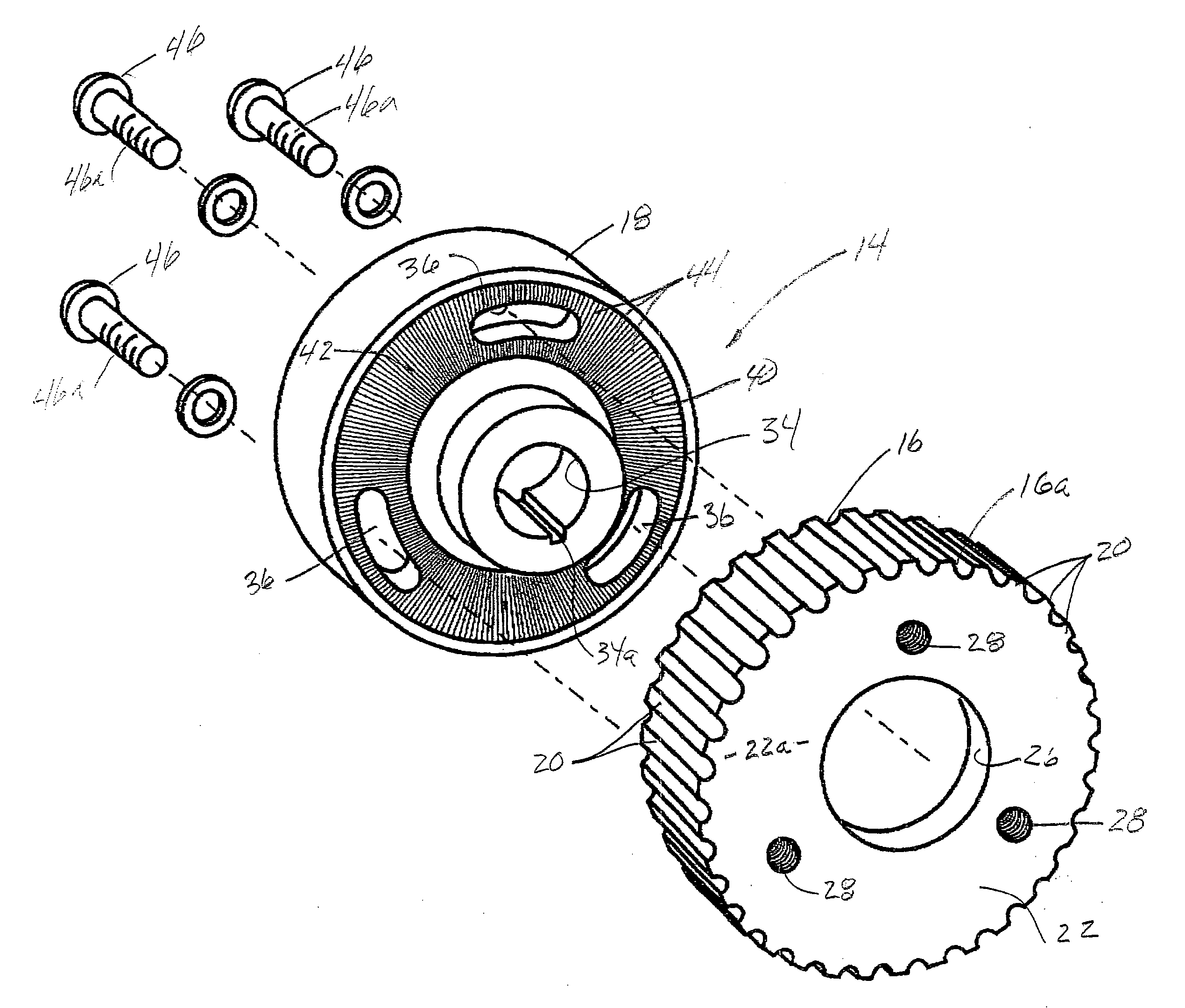
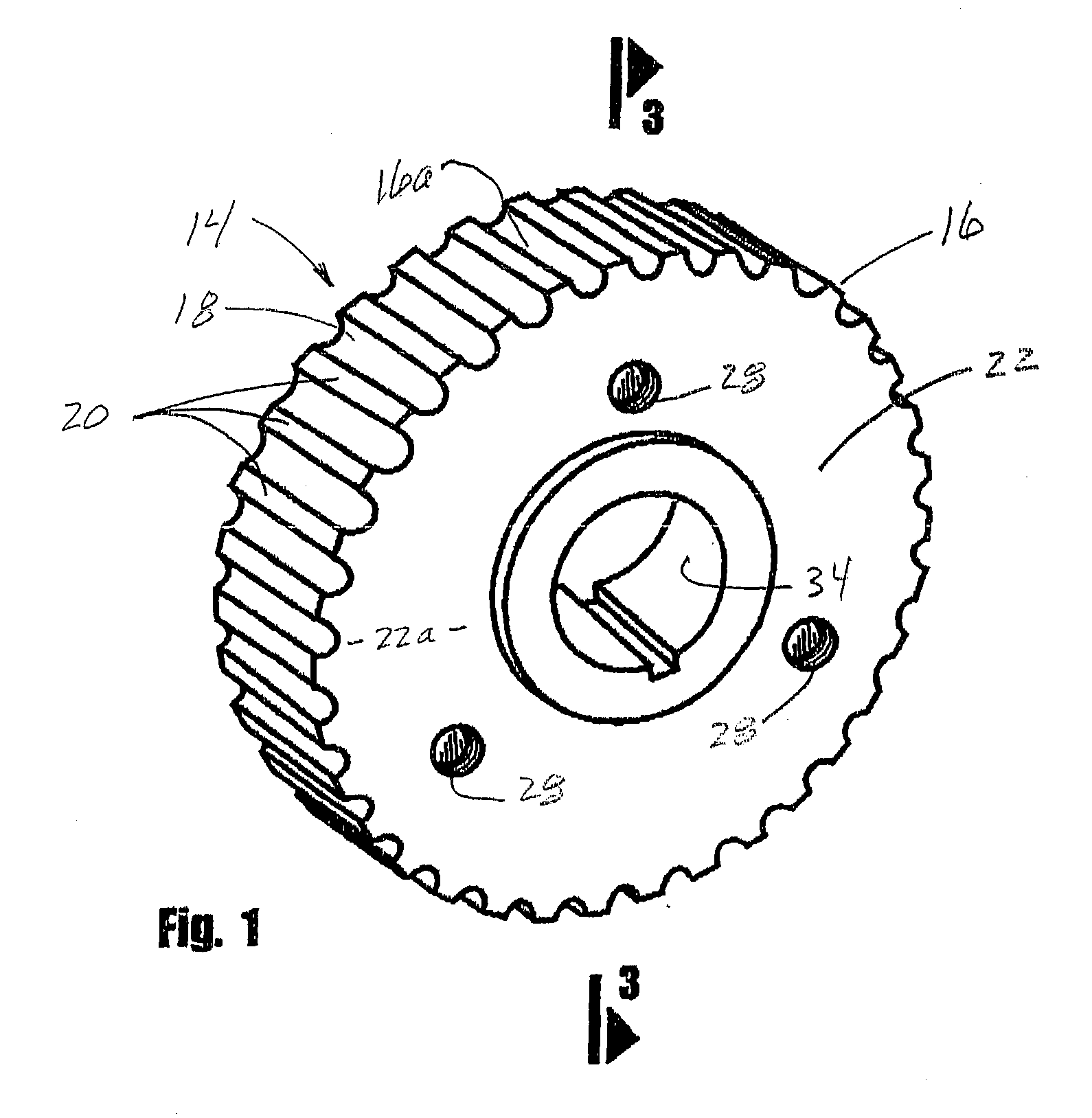
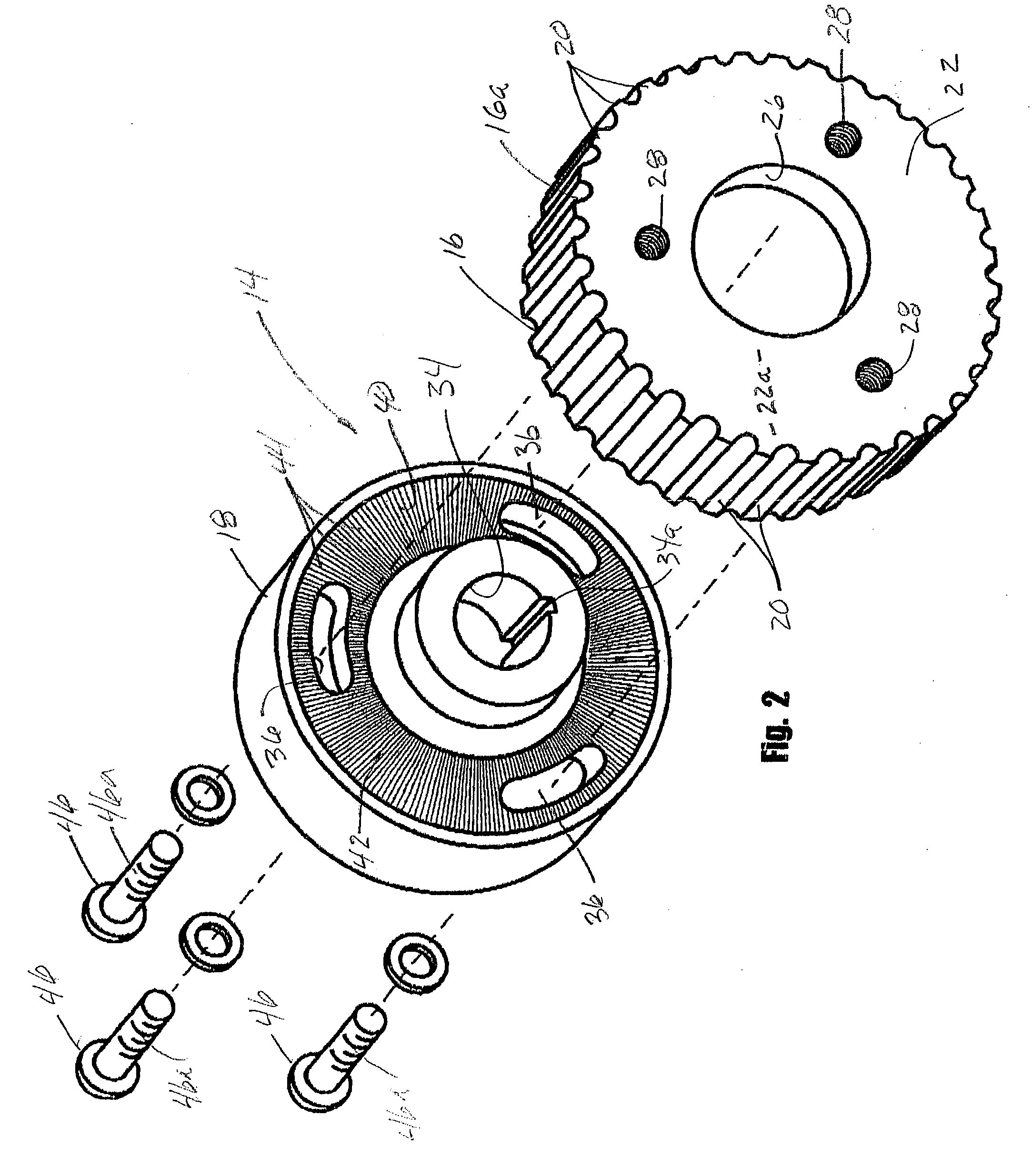
[0035] Referring to the drawings and particularly to FIGS. 1 through 5, one form of the adjustable timing gear of the invention is there shown in generally designated by the numeral 14. As best seen by referring to FIG. 2, the adjustable timing gear 14 here comprises a gear member 16, a hub member 18 and connector means for interconnecting the hub member with the gear member. As shown in FIGS. 1 and 2, gear member 16 has a peripheral portion 16a having a multiplicity of spaced-apart timing belt engaging teeth 20 formed thereon and an innermounting web 22 connected to peripheral portion 16a and extending inwardly therefrom. The peripheral portion and the inner mounting web cooperate to define a generally cylindrically shaped internal chamber 24 (FIG. 3), which, in a matter presently to be described, telescopically receives the hub member 18 of the adjustable timing gear assembly.

[0036] Inner mounting web 22 has an outer surface 22a, an inner surface 22b (FIG. 7), a central opening 26...


PUM


Abstract

An adjustable timing gear assembly and the method of making same that can readily be adjusted in the field in a manner to permit precise cam timing adjustments without having to remove the engine timing belt from the gear member of the apparatus. Importantly, the gear assembly includes strategically located and configured mating serrations that function to positively prevent accidental relative rotation between the gear member and the hub member of the device which is connected to the engine camshaft

Description

[0001] 1. Field of the Invention[0002] The present invention relates generally to valve timing for internal combustion engines. More particularly, the present invention concerns an adjustable timing gear for accomplishing precise camshaft adjustments.[0003] 2. Discussion of the Prior Art[0004] Most internal combustion engines use intake valves to control the entry of combustible gases into the combustion chamber of the engine for ignition by a spark generated by a spark plug. Following combustion of the combustible gases within the combustion chamber, exhaust valves are used to control the escape of exhaust gases resulting from the combustion. Typically, both the intake and exhaust valves are controlled by cam lobes provided on the engine camshaft. Pistons reciprocally movable within the combustion chamber are driven by the combustion of the combustible gases to cause the rotation of a crankshaft. The crankshaft functions to translate the up-and-down motion of the piston into a rota...

Claims


Application Information

Patent Timeline
Patent Type & Authority Applications(United States)
IPC IPC(8): F16H55/17F16H57/00
CPCF01L1/026F01L2103/02Y10T74/19F16H55/171F16H57/0025F01L2800/17F01L2303/02
Inventor BOURNE, EDWARD T.DUROUSSEAU, SHERMAN A.
Owner BOURNE EDWARD T
Learn More