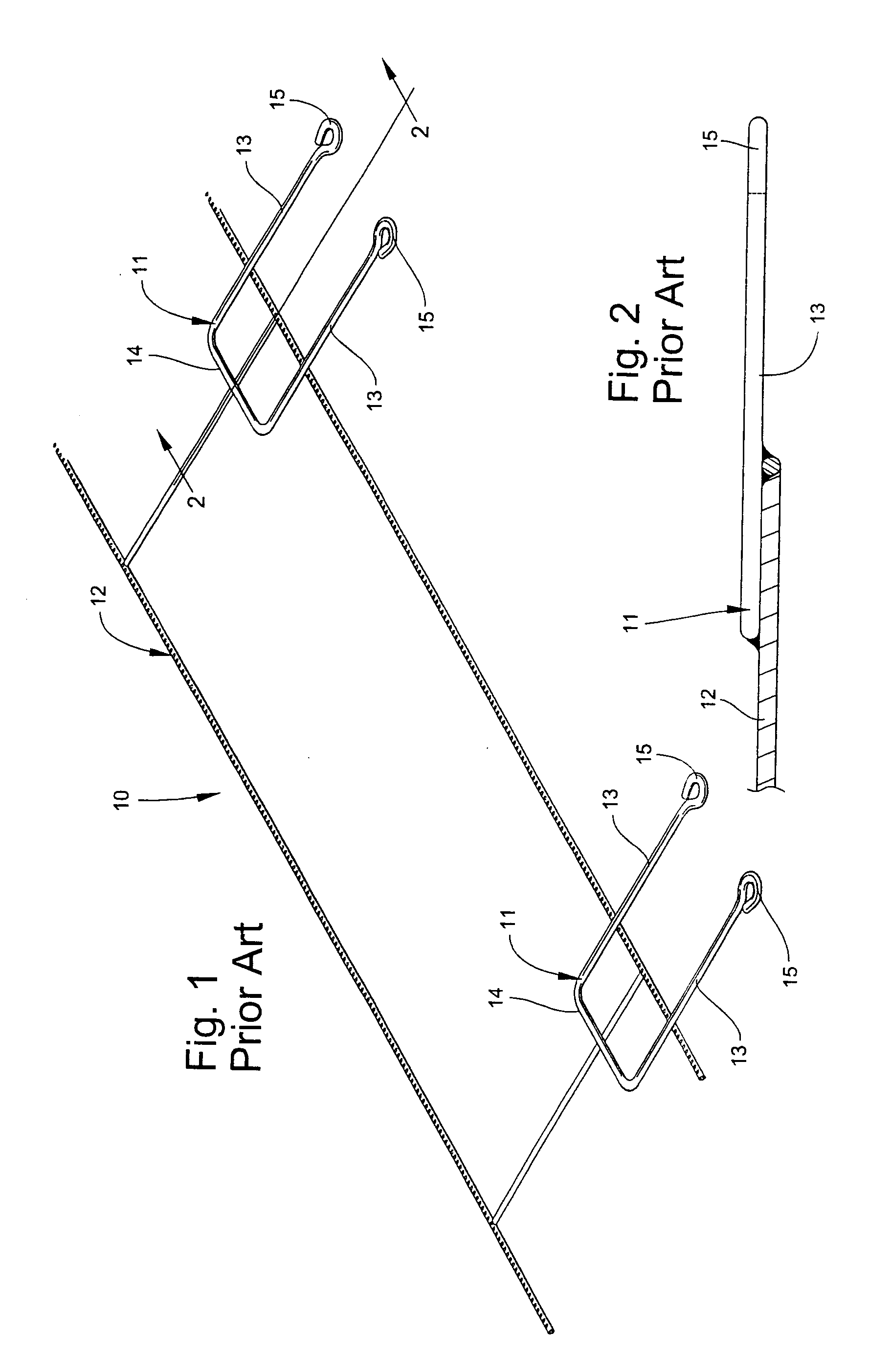
[0031] As shown in FIG. 2, the U-shaped bracket 11 is welded to one surface of the support frame 12, and occupies a different horizontal plane than the support frame 12. This increases the overall thickness of the anchor 10, resulting in less space available for filling mortar. The support frame 12 is typically comprised of a
metal wire having a thickness of 0.148 inch, and the bracket 11 generally has a thickness of 0.187 inch, yielding a
total thickness for anchor 10 of 0.335 inch. The typical concrete block
mortar joint has a thickness of 0.375 inch. Thus, the anchor 10 occupies at least 89% of the thickness within the
mortar joint. The relatively limited area available for mortar within the
mortar joint has a detrimental effect on the structural stability of the wall structure. In addition, the U-shaped bracket 11 of masonry anchor 10 is welded at three points on the support frame 12, increasing time and costs associated with producing the anchor 10, in comparison with the present invention.
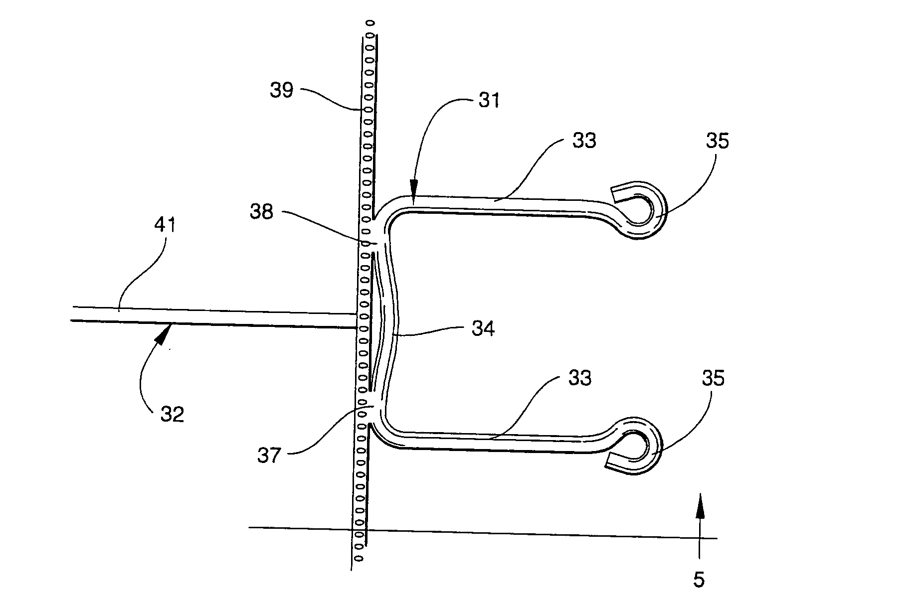
[0033] A preferred embodiment of the masonry anchor according to the present invention is illustrated in FIG. 4, and shown generally at reference numeral 30. The masonry anchor 30 comprises a U-shaped bracket 31 affixed to a support frame 32 formed of two parallel
metal wires 39, 40 joined by a plurality of transverse metal wires 41. The transverse wires 41 are connected to the wires 39, 40 at equally spaced apart intervals to form a ladder-type frame. The transverse wires 41 are spaced apart such that the support frame 32 correspondingly aligns with the top transverse surface of a typical concrete block wall 42, as shown in FIG. 9. The U-shaped bracket 31 includes a pair of parallel elongate arms 33 connected by a cross wire 34 extending transversely from the support frame 32. Eyes 35 are formed at the ends of the elongate arms 33, and shaped to receive a respective hook 46 from a complimentary connecting member such as a wall tie 36, as shown in FIG. 9. As shown in FIGS. 6 and 7, the eyes 35 preferably have a true circle or lollipop shape that reduces the area in which the hook 46 of the wall tie 36 can move. The restricted movement of the hooks 46 within the eyes 35 improves stability of the finished wall structure.
[0034] The cross wire 34 of the bracket 31 is bent inwardly at the center to produce two spaced apart
welding points 37, 38 extending out slightly further than the rest of the cross wire 34. The area between the
welding points 37, 38 forms a concavity with relation to the support frame 32. As such, the two points 37, 38 are the only areas of the cross wire 34 that contact the support frame 32, thus providing two discrete
welding points 37, 38 for easily and efficiently welding the bracket 34 to the support frame 32 in precise alignment with the thickness of the support frame 32 during a single welding operation.
Welding the bracket 31 to the support frame at only two points 37, 38 expends less energy than welding all of a linear cross wire to the support frame. In addition, attempting to weld a linear cross wire to the support frame results in a weaker connection between the bracket and support frame.
[0035] As shown in FIGS. 6 and 7, the cross wire 34 is welded to the wire 39 at the two spaced apart points 37, 38, that are on opposite sides of the point where the transverse wire 41 intersects and is welded to wire 39, as shown in FIG. 4. As shown in FIG. 5, the U-shaped bracket 31 resides in the same horizontal plane as the support frame 32, thereby maximizing available space for mortar filling. Because the masonry anchor 10 occupies a single horizontal plane, a
heavy duty gauge metal wire, having, for example, a thickness of 0.187 inches can be used for all parts of the anchor 40. As such, masonry anchor 40 can be comprised completely of the 0.187 inch gauge metal wire and still occupy less than fifty percent of the typical 0.375 inch thickness of a mortar joint, while prior art bi-planar anchors, such as anchor 10, typically require the use of a lesser gauge wire, such as 0.148 inch, for the support frame in order to provide just minimal space for the mortar. In addition, prior art anchor 10, due to the length of arms 13, requires more metal wire material to produce its U-shaped bracket 12, than does bracket 31 in anchor 30.
[0040] The bracket 51 can be efficiently made in a
welding process in which a plurality of the brackets 51 are loaded, one on top of the other, into a
magazine. The support frame 52 is positioned on a conveyor
proximate the
magazine. Brackets 51 are fed one by one through an exit at the bottom of the
magazine by a
pneumatic cylinder. A clamp ensures that the ejected bracket 51 is aligned in the same horizontal plane with the support frame 52, and the ejected bracket 51 is welded to support frame 52 at welding points 57, 58. The support frame 52 is indexed down the conveyor, and another bracket 51 is ejected from the magazine and welded to the support frame 52. The support frame 52 is indexed along the conveyor such that a bracket 51 is welded to the support frame 52 at approximately sixteen inch intervals.