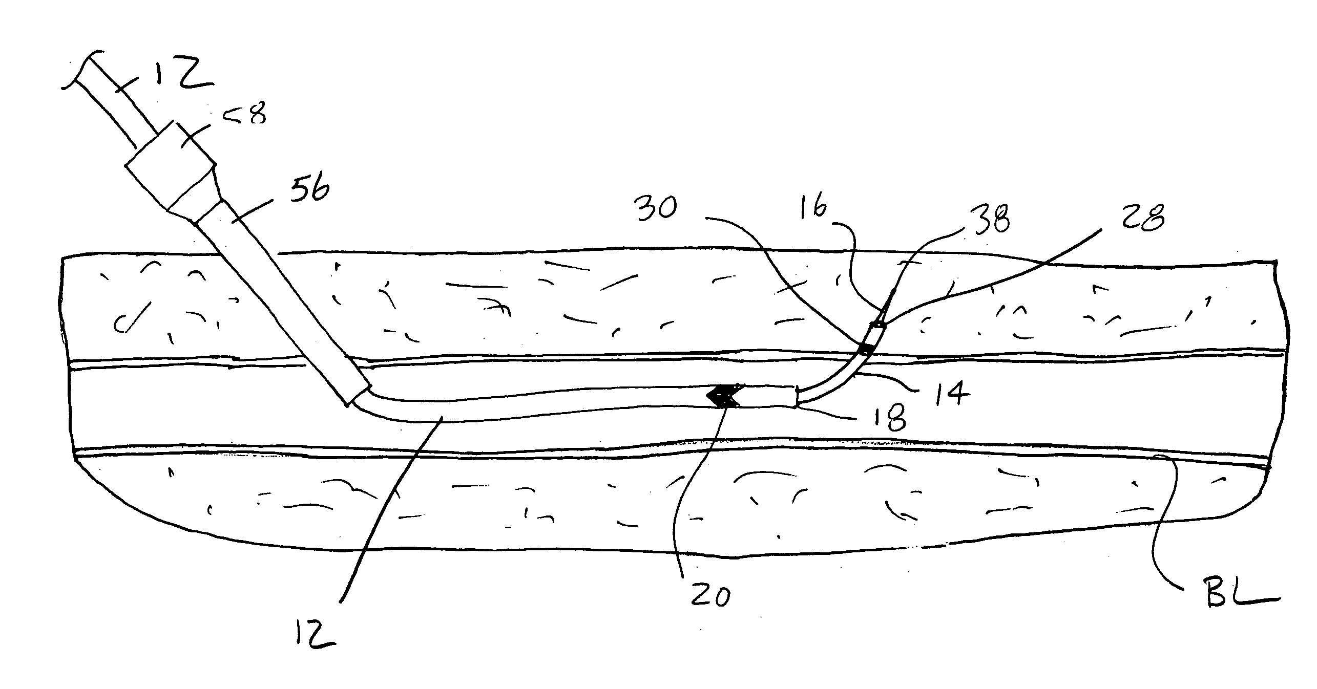
[0012] In particular, the present invention provides improved techniques for accessing a luminal target site from at least two sides, e.g., the upstream side and the downstream side from a target site in the vasculature. Such two-sided access permits multiple and / or sequential treatments to be formed at the target site from both sides. For example, a catheter could be placed on one side of the treatment site to provide for
occlusion and / or aspiration of the target site. A catheter placed on the opposite side of the target site could then be used to dislodge stenotic material and direct that dislodged material into the downstream catheter. A second example would be to use first and second catheters having balloons or other occlusive elements at their distal ends. The two catheters could be used to isolate a treatment region within the
blood vessel permitting the introduction of thrombolytic agents, embolectomy devices, or the like, with a greatly
reduced risk of emboli release. These two techniques are offered as examples only, and a wide variety of other combination treatments will be enabled using the access and treatment methods and apparatus of the present invention.
[0015] To overcome these difficulties, it is desirable to stabilize the catheter within the body lumen prior to and during advancement of the penetrating element through the overlying tissue. This can be achieved in various ways. Most simply, an anchor such as a relatively short
balloon can be provided near the distal end of the catheter to hold the catheter in place (at least at its distal end) while the penetrating element is advanced. While an improvement, anchoring the catheter only at its distal end does little to reduce deformation of the catheter and / or body lumen over its proximal regions. Thus, in some cases, it may desirable to anchor the catheter over a major portion of its length, and optionally its entire length, e.g., using a
balloon which extends over the entire length of the catheter. As a further alternative, the catheter may be selectively stiffened after it is deployed. Stiffening could be provided by inflating the walls of the catheter, actuating a mechanical linkage within the catheter which locks the catheter shape in place, and the like. As a further alternative, the catheter could be formed at least partly from a highly flexible structure, such as a
coil spring, with one or more axial wires or other tethers which prevent elongation of the structure as the penetrating element is passed therethrough. As a still further alternative, co-axial support tubes and other structures could also be provided for selectively stiffening the catheter to enhance pushability of the penetrating device therethrough.
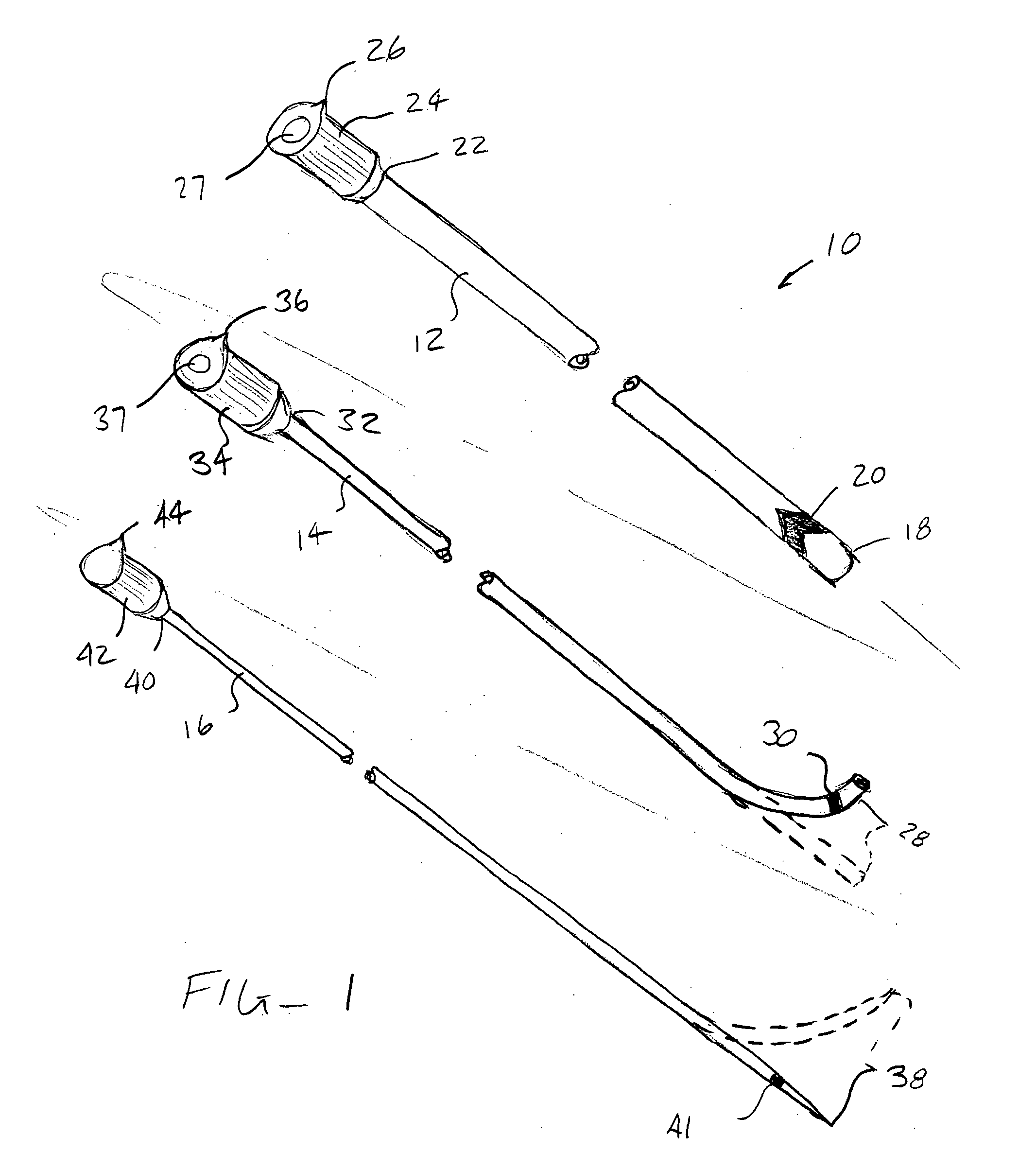
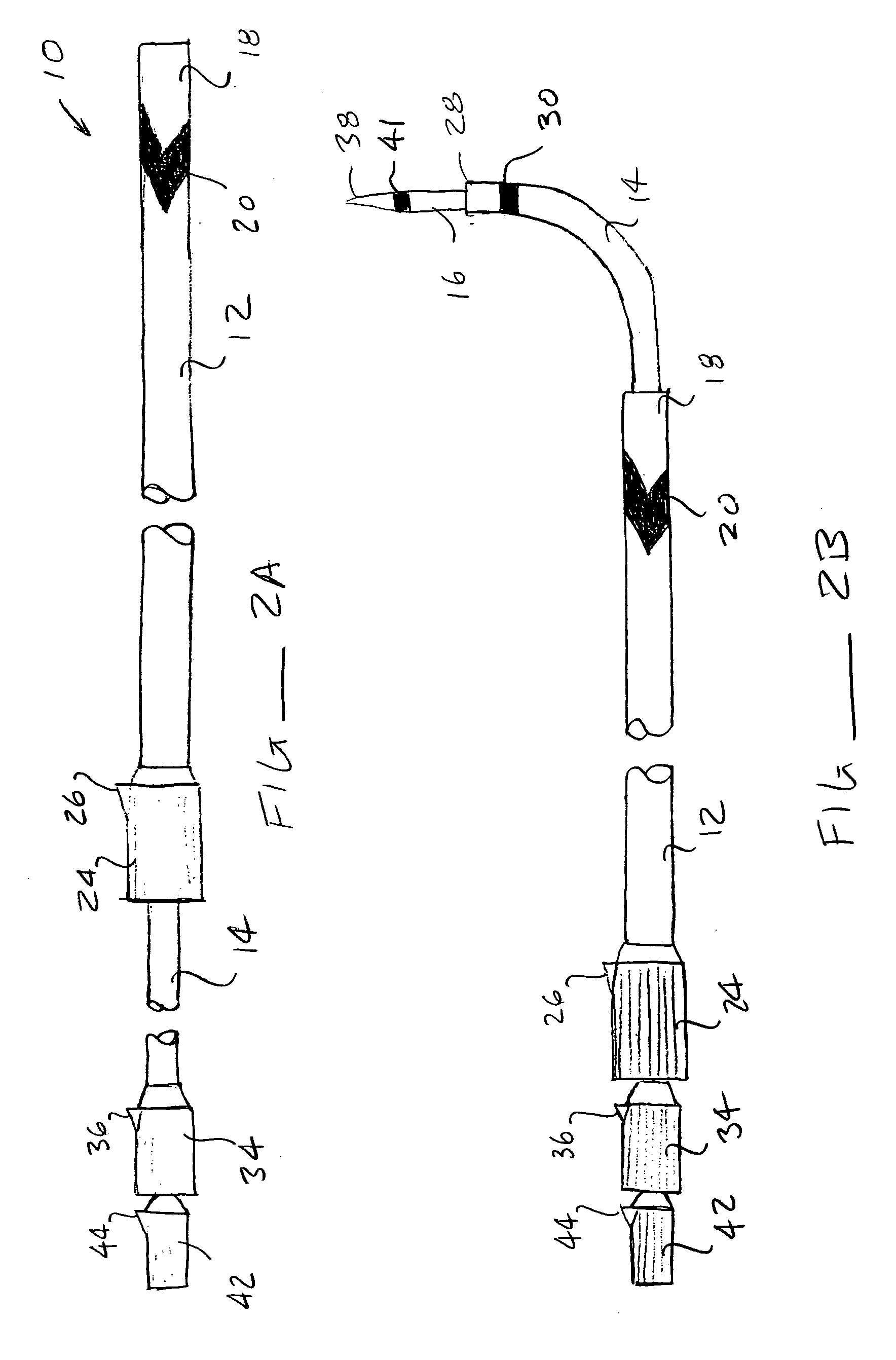
[0016] The penetrating device preferably comprises a
guide tube having a lumen therethrough where the penetrating element is removably disposed within the lumen of the
guide tube. In this way, after the penetrating device has been advanced through the luminal wall to form the second access penetration, the penetrating element can be withdrawn to leave the lumen in the
guide tube available to define a guide path between the second access penetration and the first access penetration. In particular, the lumen in the guide tube will be useful for positioning a guidewire, catheter, filament, wire,
optical fiber, or other flexible elongate member between the two access penetrations. After the guidewire or other member is placed through the guide tube, the guide tube can be withdrawn. Optionally, a conventional access sheath may then be placed over the guidewire so that catheters and other conventional tools may then be introduced into the vascular or other body lumen through the introducer sheaths on both sides of the target site. More importantly, a single guidewire is now in place for introduction of the interventional catheters and other tools from both sides of the target site. The single guidewire may be appropriately tensioned to facilitate introduction, e.g., using a clamp or other tool or by applying manual tension. Moreover, the
elimination of a second guidewire near the target site greatly simplifies deployment and use of all diagnostic and interventional tools.
[0021] In an exemplary embodiment, the advancable means comprises a guide tube having a penetrating element in a lumen thereof. The penetrating element may be a
metal e.g., stainless steel, Elgiloy.TM., or Nitinol.TM., or plastic stylet having a sharpened distal tip where the tip extends forwardly of the guide tube. Alternatively, the advancable means can be an integral structure having a sharpened distal tip. The use of a separate guide tube is advantageous, however, since withdrawal of the penetrating element leaves a lumen accessible for placement of a guidewire after the second access penetration has been formed. Optionally, the catheter may comprise a
balloon or other expandable anchor disposed at or near its distal end. Further optionally, the device may comprise an support tube for placement over or through the catheter. The support tube is advantageous in that it provides additional column support to the catheter to facilitate pushing of the advancable means from the catheter through the luminal wall.


