
Custom-moldable wrist splint

a wrist splint and custom-made technology, applied in the field of orthopaedic medicine, can solve the problems of numbness, tingling and pain in the fingers and hands, affecting the function and causing pain and parasthesia in the arm and shoulder, and achieve the effect of easy placement and removal of the hand and wris

Inactive Publication Date: 2004-09-09
BSN MEDICAL INC
View PDF0 Cites 45 Cited by
  • Summary
  • Abstract
  • Description
  • Claims
  • Application Information

AI Technical Summary

Benefits of technology

[0012] It is another object of the invention to provide a wrist splint assembly that can be easily placed on and removed from the hand and wrist by the patient.

Problems solved by technology

Continuous constriction of the median nerve causes it to gradually deteriorate, which in turn causes numbness, tingling and pain in the fingers and hand.
Occasionally, such constriction also produces pain and parasthesia in the arm and shoulder.
If left untreated, carpal tunnel syndrome can ultimately cause the muscles on the affected hand to weaken and atrophy.
Pregnant women and persons with diabetes or hypothyroidism are at an increased risk of developing carpal tunnel syndrome.
Splints formed from thermosetting materials cannot be used without a heat source, and the splints are susceptible to over-or-underheating.
In addition, body heat can soften or at least increase the flexibility of the splint, which decreases the effectiveness of the protection offered by the splint.

Method used


Image

  • Custom-moldable wrist splint
  • Custom-moldable wrist splint
  • Custom-moldable wrist splint

Examples


Embodiment Construction

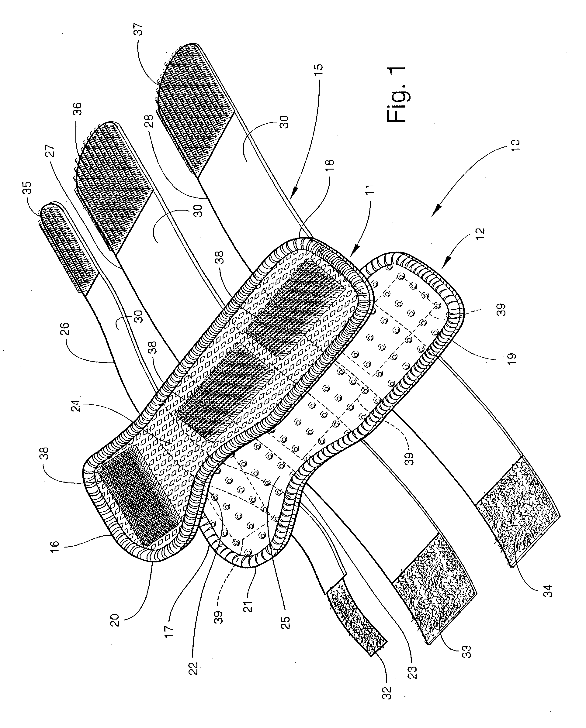
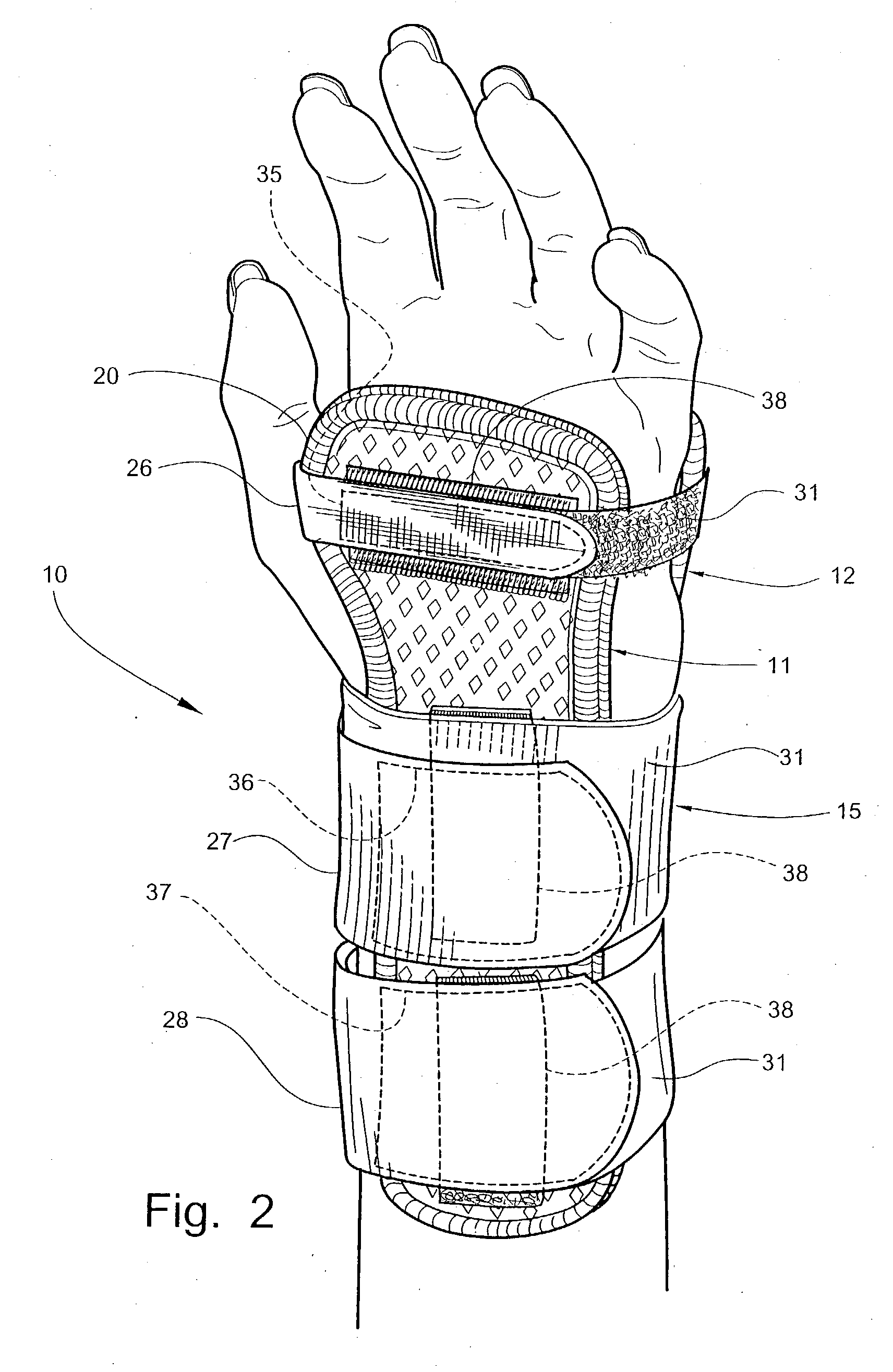
[0050] Referring now specifically to the drawings, a wrist splint assembly according to one preferred embodiment of the invention is illustrated in FIG. 1 and shown generally at reference numeral 10. The splint assembly 10 includes two splints 11 and 12 which, as described more fully below with reference to FIGS. 10 through 13, are custom-molded to fit against the dorsal and volar aspects of the hand and wrist of a wearer. The splints 11 and 12 are held in place by a strap assembly 15.

[0051] Referring again to FIG. 1, the splints 11 and 12 include upper end portions 16 and 17, which are integrally formed with respective elongate lower end portions 18 and 19. The upper end portions 16 and 17 are wider than the lower end portions 18 and 19, and define rounded, convex side edges 20 and 21, respectively. As is shown in FIGS. 2 and 3, the increased width and rounded side edges 20 and 21 permit the respective upper end portions 16 and 17 to extend across and support the second through fou...


PUM


Abstract

A wrist splint assembly for being custom-fitted to a hand and wrist to be supported. The wrist splint assembly includes a first splint for being positioned against and formed to the volar aspect of the hand and wrist, and a second splint for being positioned against and formed to the dorsal aspect of the hand and wrist. Each of the first and second splints defines a concave side edge extending inwardly toward the longitudinal axis of the splint for permitting ease of movement of the thumb and associated carpometacarpal joint of the hand against which the splint is positioned. Each splint also includes an inner cushion layer, an initially flexible intermediate layer overlying the inner cushion layer, and a flexible outer layer. The intermediate layer is a substrate impregnated with a moisture-curable resin that hardens upon curing to form a rigid structure of the substrate that retains a shape into which it is molded during curing for maintaining the flexible inner cushion layer in a conforming shape against the hand and wrist. A support retains the first and second splints in position on the hand and wrist during use of the splint assembly.

Description

TECHNICAL FIELD AND BACKGROUND OF THE INVENTION[0001] This invention relates generally to the field of orthopedic medicine and more specifically to a custom-moldable wrist splint and a method for using such a splint to relieve and treat the symptoms of carpal tunnel syndrome.[0002] Carpal tunnel syndrome occurs as a result of chronic irritation to the median nerve. The median nerve and the tendons that connect the muscles of the forearm to the fingers of the hand pass through the carpal tunnel. The carpal tunnel is a passageway defined by the eight carpal bones of the wrist and the transverse carpal ligament, which interconnects the hook of the hamate and the tubercle of the trapezium. Carpal tunnel syndrome results when the median nerve becomes constricted within the carpal tunnel, usually by the swelling of the tendons. Such constriction pushes the median nerve against the transverse carpal ligament located directly above the nerve.[0003] The median nerve relays sensation from the...

Claims


Application Information

Patent Timeline
Patent Type & Authority Applications(United States)
IPC IPC(8): A61F5/01
CPCA61F5/05866A61F5/0118
Inventor DARCEY, THOMAS D.
Owner BSN MEDICAL INC
Learn More