
Method for controlling slitter-scorer apparatus

Inactive Publication Date: 2004-08-19
ISOWA IND CO LTD
View PDF11 Cites 50 Cited by
  • Summary
  • Abstract
  • Description
  • Claims
  • Application Information

AI Technical Summary

Benefits of technology

[0020] Another object of the present invention is to provide a method for controlling a slitter-scorer apparatus in which a feed line for a paperboard sheet does not need to be stopped when an order specification for cutting or scoring for the paperboard sheet has been changed, and which can prevent meandering of a paperboard sheet, thereby increasing available yield percentage of the paperboard product.
[0021] Still another object of the present invention is to provide a method for controlling a slitter-scorer apparatus which can control the operative level for the slitter and / or scorer precisely in response to the change of the order specification for cutting or scoring the paperboard sheet.
[0032] Furthermore, the length of the movement path of the slitter and / or scorer to the operative position will be shortened by controlling the movement of said slitter and / or scorer such that said slitter and / or scorer either comes into sliding contact with or is apart slightly from said surface of the paperboard sheet, so that it does not need to stop a feed line for a paperboard sheet, thereby reducing a setup time for production.
[0033] According to the method for controlling a slitter-scorer apparatus of the present invention, the time needed for the movement of the slitter and / or scorer to the operative level upon an order change will be shortened by positioning said slitter and / or scorer in a standby position which is more proximal to said surface of said paperboard than said retracted level while said slitter and / or scorer does not work upon said surface of said paperboard, thereby increasing the available yield percentage of the paperboard product, even when the slitter and / or scorer is moved to the operative level after an operation start command has been received.

Problems solved by technology

However, a slitter-scorer apparatus of the prior art suffers from the drawback that accurate positioning of the slitter and / or scorer in a vertical direction is difficult to achieve upon the order specification change.
The first problem is relates to the required setup time for the slitter-scorer.
More particularly, upon the paperboard order change, the slitter and / or scorer is transferred vertically by using an air piston / cylinder which merely can control its piston's position point-to-point, that is between an extended position and contracted position apart from each other by the distance of the piston's stroke, so that accurate positioning of the slitter and / or scorer in close proximity to the surface of the paperboard is difficult to achieve.
This apparatus, although it produces waste paperboard until the setup has been completed, may cause meandering of a paperboard sheet, thereby potentially having an adverse effect which leads to an interruption of processing.
The second problem is related to the reduction of available yield percentage of the paperboard product.
The longer the setup time takes, the lower the available yield percentage, since paperboard sheet supplied during the setup time will be scrapped.
In addition, in the typical slitter-scorer apparatus of the prior art which transfers the slitter and / or scorer vertically from its retracted level to its operative level just before the processing, unnecessary paperboard is supplied during movement of the slitter and / or scorer to the operative level in response to the operation start command has been received, resulting in a further reduction in the available yield percentage of the paperboard product.
The third problem is that there are difficulties in dealing with fluctuations in the condition of processing in response to the order change and with disturbance of the slitter-scorer apparatus itself or quality of the paperboard.
More particularly, the fluctuations in the condition of processing in response to the order change include change of the scoring pressure, and the disturbance of the slitter-scorer apparatus includes depth of wear of the slitter blade and deflection of the shaft which supports the slitter blade, and disturbance of the quality of the paperboard includes fluctuations of moisture content and quality of the paper.

Method used


Image

  • Method for controlling slitter-scorer apparatus
  • Method for controlling slitter-scorer apparatus
  • Method for controlling slitter-scorer apparatus

Examples


Embodiment Construction

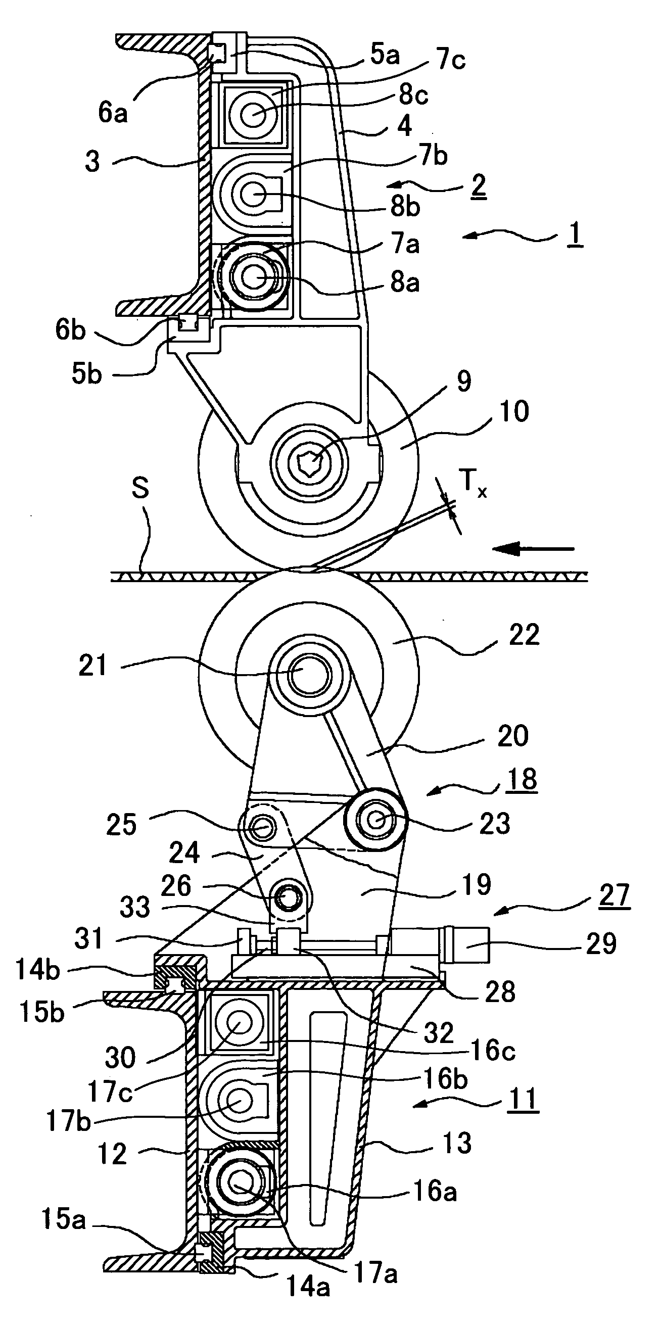
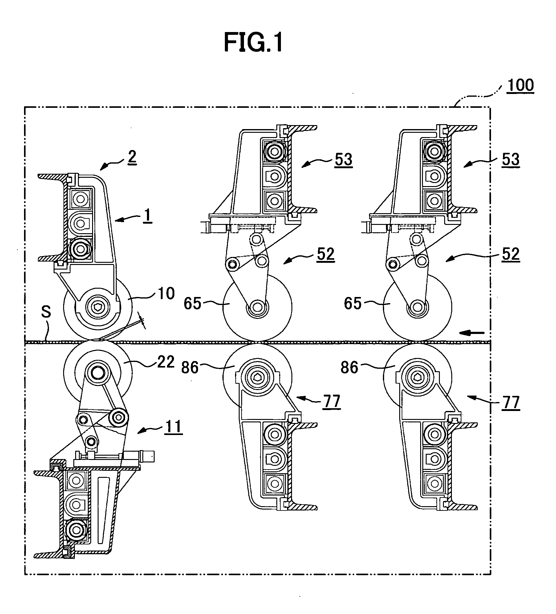
[0053] These and other features and advantageous of the invention will be clarified by the following description of the preferred embodiments and reference to the associated drawings. It will be appreciated that although a slitter-scorer apparatus including a plurality of slitters and scorers in series is disclosed, the present invention is applicable to either a slitter apparatus or a scorer apparatus.

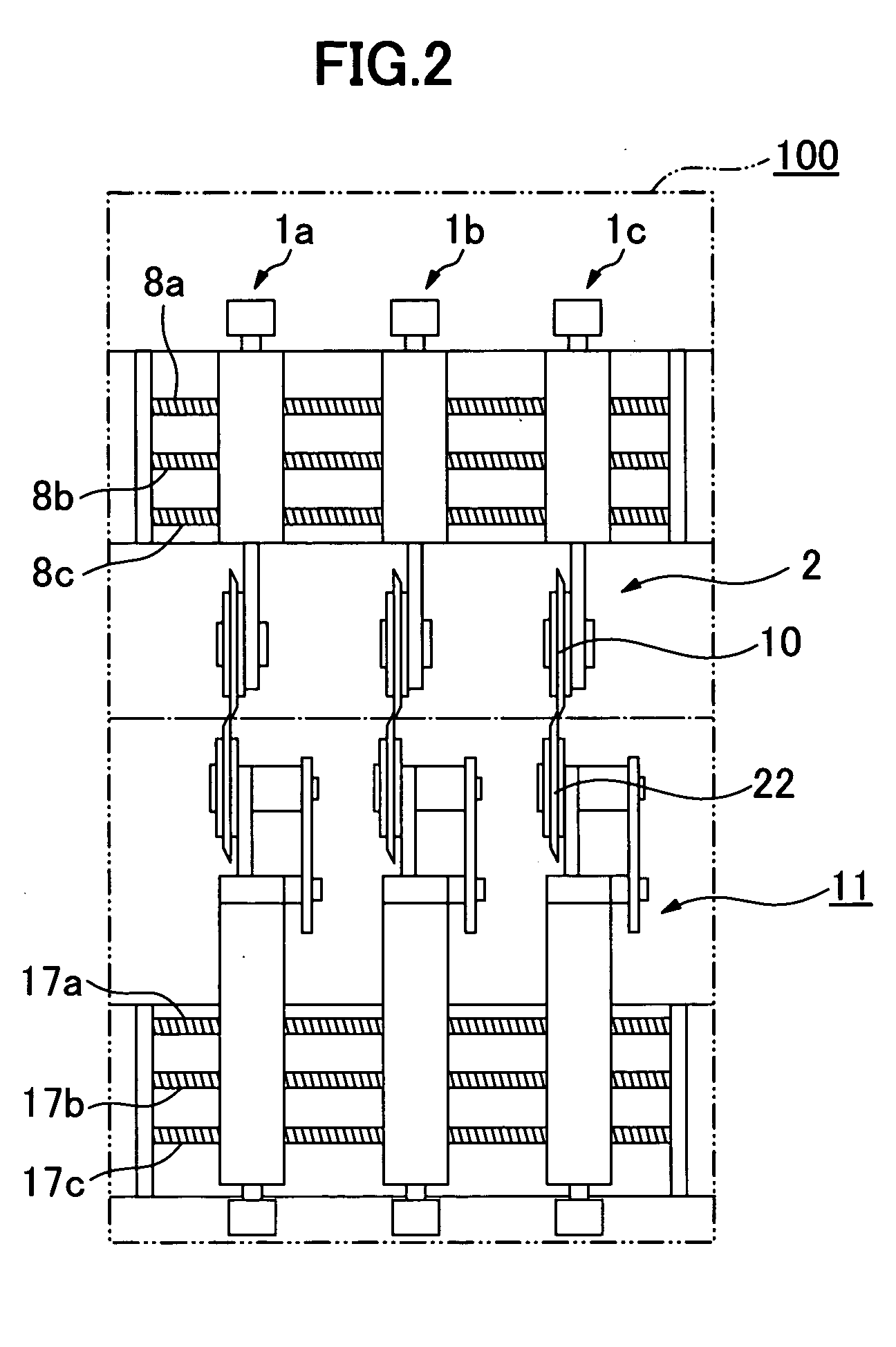
[0054] As can be seen in FIG. 1, a slitter-scorer apparatus 100 includes two sets of scorers 52 disposed in the upstream of the feed line of a paperboard sheet S, and one slitter 1 in the downstream thereof. As can be seen in FIG. 2, the slitter 1 comprises three sets of slitters 1a, 1b and 1c spaced apart from each other in a widthwise direction. Similarly, each of the scorers 52 comprises three sets of scorers 52a, 52b and 52c disposed in a widthwise direction. Each of the scorers 52a, 52b and 52c as well as the slitters 1a, 1b and 1c can be moved in a widthwise direction independen...


PUM

PropertyMeasurementUnit
Distanceaaaaaaaaaa
Depthaaaaaaaaaa

Abstract

A method for controlling a slitter-scorer apparatus in which a feed line for a paperboard sheet does not need to be stopped when order specification of cutting or scoring for the paperboard sheet has been changed, thereby reducing a setup time, is proposed. A method for controlling a slitter-scorer apparatus including steps of supplying a paperboard sheet along a feed line, and moving a slitter or a scorer in a vertical and / or a widthwise direction to a operative level where the surface of said paperboard sheet is processed thereby wherein: movement of said slitter and / or scorer is controlled such that said slitter and / or scorer either come into sliding contact with or is apart slightly from said surface of the paperboard sheet.

Description

[0001] This invention generally relates to a method for controlling slitter-scorer apparatus, more particularly to such a method that can prevent meandering of a paperboard sheet, thereby increasing available yield percentage of the paperboard product and decreasing setup time for production.DESCRIPTION OF RELATED ART[0002] In a typical process for manufacturing a corrugated fibreboard container box, a continuous corrugated fibreboard or paperboard sheet web such as a single surface paperboard, a double surface paperboard, or a composite double surface paperboard etc. is fed along a feed line, then cut along a direction in which the sheet is fed, in some cases being scored as well, and thereafter assembled into a corrugated fibreboard container.[0003] A slitter-scorer apparatus comprises a plurality of slitters which slit or cut a paperboard in the sheet feeding direction at desired widthwise positions, and a plurality of scorers which score the paperboard in a machine direction at ...

Claims


Application Information

Patent Timeline
IPC IPC(8): B26D1/20B26D5/02B26D7/26B31F1/20
CPCB26D7/2628B26D5/02Y10T83/7872Y10T83/04Y10T83/7859Y10T225/14Y10T83/7847Y10T83/0341Y10T83/0581Y10T83/0378E03F5/0407E03F5/041
Inventor ADACHI, NOKIHISANAITOU, MINORUKAMIMURA, TADAO
Owner ISOWA IND CO LTD
Learn More