
Solar cell and fabrication method thereof, interconnector for solar cell, solar cell string, and solar cell module

a technology of solar cells and interconnectors, applied in the field of solar cells, can solve the problems of brittle solder, disadvantage of appearance degradation, and the possibility of degradation of adherence between solar cells

Inactive Publication Date: 2004-08-12
SHARP KK
View PDF9 Cites 35 Cited by
  • Summary
  • Abstract
  • Description
  • Claims
  • Application Information

AI Technical Summary

Benefits of technology

The present invention relates to a solar cell that is lead-free and has improved wettability. The invention proposes a solar cell with a coated electrode using lead-free solder, such as Sn-Bi-Ag or Sn-Ag based solder. The lead-free solder has lower wettability than conventional 6:4 eutectic solder, but the thickness of the electrode coated with lead-free solder is increased. The invention aims to provide a solar cell with high reliability and improved adherence between the solar cell and the interconnector.

Problems solved by technology

There is the possibility of degradation in adherence between the solar cell and the silver electrode to which the interconnector is attached as well as the disadvantage of degradation in appearance.
If the amount of phosphorus exceeds 0.5 mass %, the solder will become brittle.
From the standpoint of property, reliability, and the like, dipping must be carried out at a temperature lower than 225.degree. C. that is the upper limit in practical usage.
If the amount of powdery glass exceeds 10%, homogenous paste cannot be obtained, rendering difficult the printing process of a solar cell.

Method used


Image

  • Solar cell and fabrication method thereof, interconnector for solar cell, solar cell string, and solar cell module
  • Solar cell and fabrication method thereof, interconnector for solar cell, solar cell string, and solar cell module
  • Solar cell and fabrication method thereof, interconnector for solar cell, solar cell string, and solar cell module

Examples


example 1 0.001 15

.largecircle. 2 Example 2 0.003 15 .largecircle. 2 Example 3 0.005 16 .largecircle. 2

[0061] It is appreciated from Table 4 that inclusion of phosphorus in the lead-free solder is advantageous in that the solder average film thickness is reduced and glossiness is exhibited at the solder surface. Also, the interconnector detachment rate can be reduced significantly, whereby the reliability of the solar cell is improved. A similar test was conducted with the coating solder of the interconnector altered to Sn--Ag--Cu based lead-free solder. No significant difference was found.

[0062]

[0063] The relationship between the average grain size of powdery glass included in the silver paste and the interconnector detachment rate after the temperature-humidity cycle test is shown in Table 5 set forth below for Examples 1, 4 and 5 of the present invention. In the examples of Table 5, the amount of phosphorous contained in the lead-free solder was 0.001 mass %. Also, the amount of powdery glass con...


PUM

PropertyMeasurementUnit
grain sizeaaaaaaaaaa
thicknessaaaaaaaaaa
opening diameteraaaaaaaaaa

Abstract

A solar cell has phosphorus included in a lead-free solder layer that covers silver electrodes. The amount of phosphorus in the lead-free solder is preferably 0.00001 to 0.5 mass %. The silver electrodes are silver paste electrodes formed by firing silver paste. A solar cell string interconnects such solar cells with an interconnector coated with the lead-free solder. A solar cell module incorporates such a string. Thus, a solar cell of high reliability, improved in wettability of lead-free solder, exhibiting thin coating of an electrode by lead-free solder, suppressed in detachment of interconnector a solar cell string, or a solar cell module can be provided.

Description

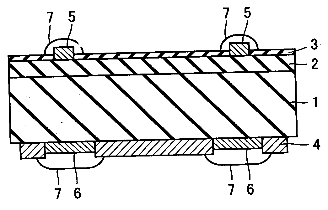
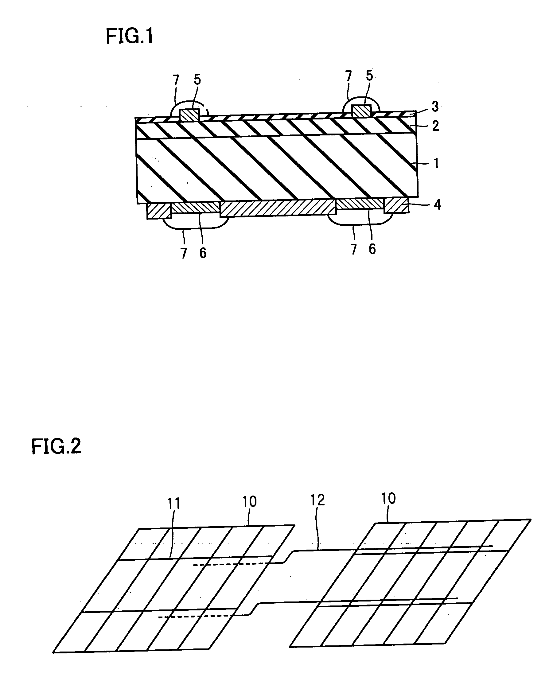
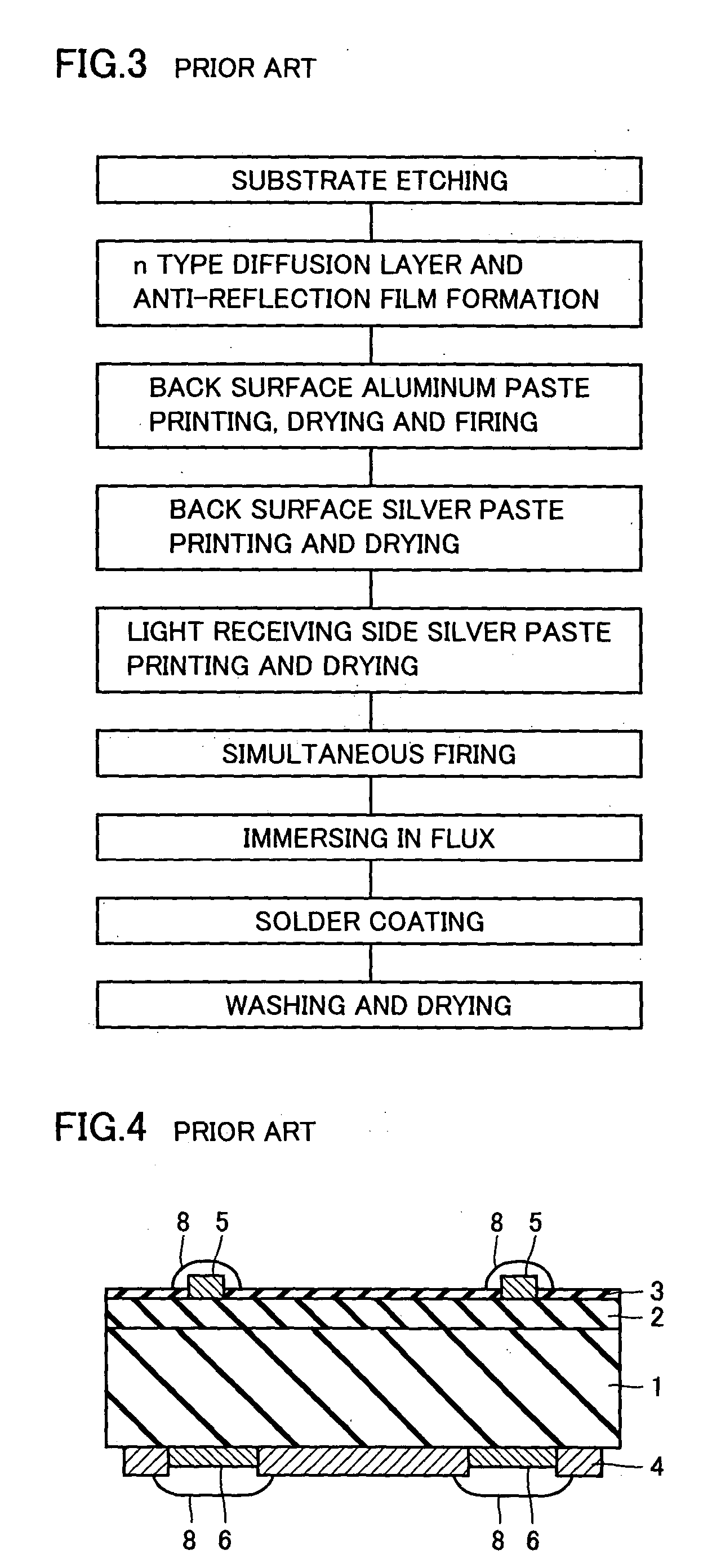
[0001] 1. Field of the Invention[0002] The present invention relates to a solar cell, particularly a solar cell having an electrode coated with lead-free solder, a fabrication method of such a solar cell, an interconnector for such solar cells, a solar cell string, and a solar cell module.[0003] 2. Description of the Related Art[0004] A schematic sectional view of a conventional solar cell in a solder coating process is shown in FIG. 4. An n type diffusion layer 2 is formed at one side, identified as the light receiving side, of a p type silicon substrate 1 subjected to etching. A major part of the region of n type diffusion layer 2 is covered with an anti-reflection film 3 directed to reduce the surface reflectance. Also, a back surface aluminum electrode 4 is formed covering the major region at the back side of p type silicon substrate 1. Silver electrodes 5 and 6 are formed at a partial region at the light receiving side of n type diffusion layer 2 and a partial region at the bac...

Claims


Application Information

Patent Timeline
Patent Type & Authority Applications(United States)
IPC IPC(8): H01L31/00H01L31/04H01L31/0224H01L31/042
CPCY02E10/52H01L31/022425Y02E10/50H01L31/0504
Inventor TANAKA, SATOSHIHIOKI, MASAOMI
Owner SHARP KK
Learn More