
Method and apparatus for web-based configuration of instrumentation, and business methods employing same

a technology of web-based configuration and business methods, applied in the field of methods and apparatus for web-based configuration of instruments, and business methods employing same, can solve the problems of time-consuming, inefficient and costly procedures with regard to both personnel and materials, and achieve the effects of rapid specification/sample rendering, quick time-to-market, and rapid implementation

Inactive Publication Date: 2004-07-22
CURTIS INSTRUMENTS INC
View PDF11 Cites 21 Cited by
  • Summary
  • Abstract
  • Description
  • Claims
  • Application Information

AI Technical Summary

Benefits of technology

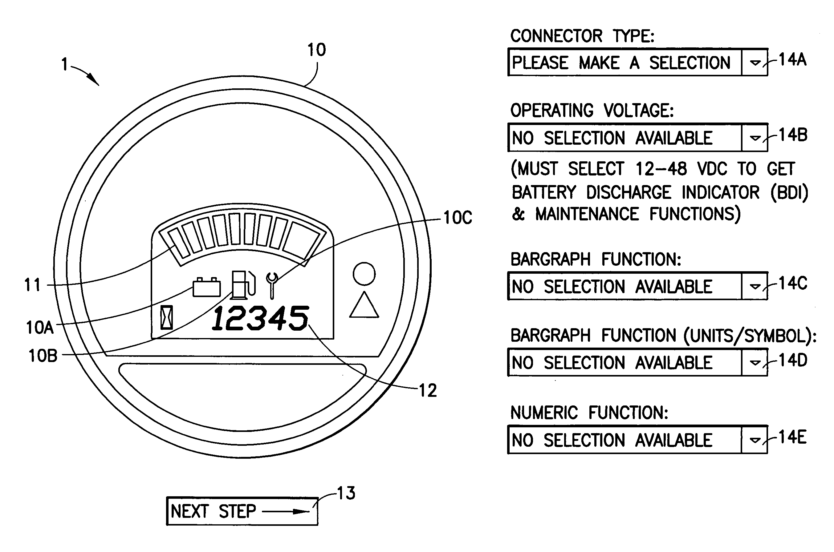
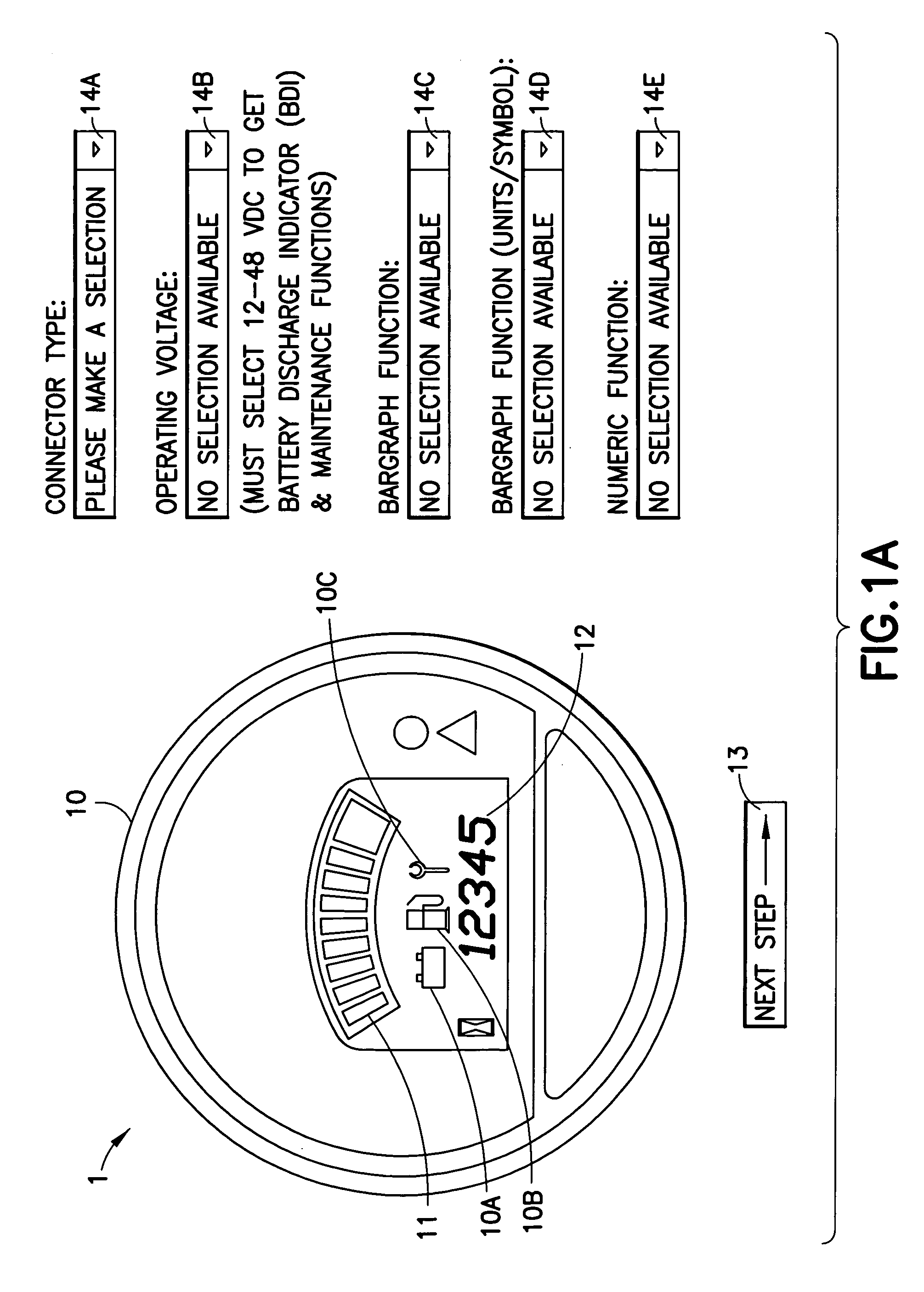
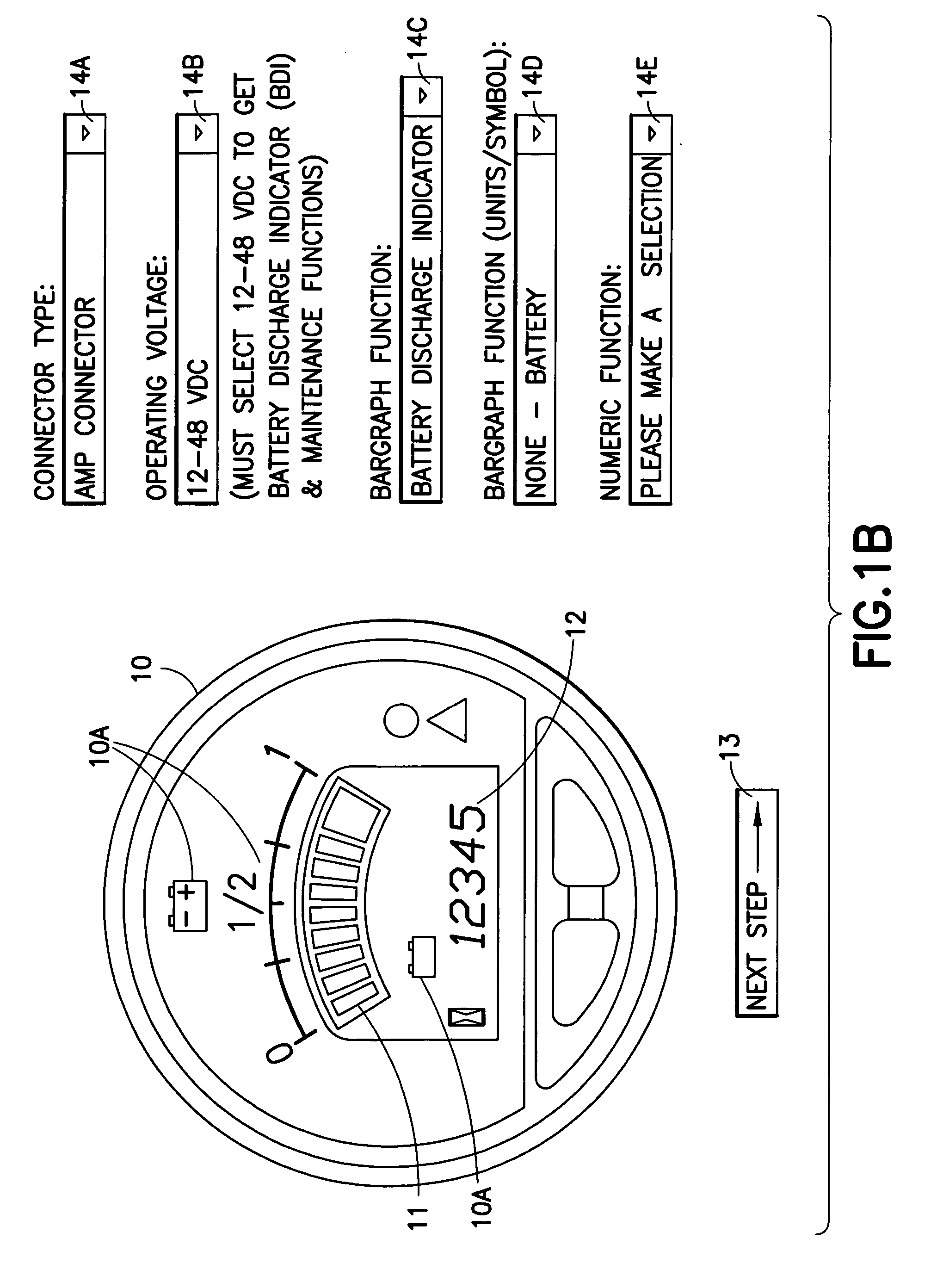
[0009] In a further aspect this invention provides a method to enable a user of a tool, such as a web tool, to specify a gauge. This method includes displaying an image of a selected gauge type while displaying, in association with the selected gauge type, a set of visual aids, referred to herein as icons and advisories, corresponding to configurable gauge parameters, also referred to as functions; enabling the user to specify individual ones of the configurable gauge functions using the set of visual aids with a drag and drop technique for selecting individual visual aids from the set of visual aids and associating a selected visual aid with a configurable gauge function. The method further includes outputting a data file for use in preparing at least one sample of the selected gauge type in accordance with the gauge functions corresponding to the selected visual aids. In one embodiment the configurable gauge functions are located at fixed locations in the image, while in another embodiment the configurable gauge functions are located at user selected locations in the image. The configurable gauge functions may have a fixed size and shape, or they may have at least one of a size and a shape that is selected by the user.
[0011] An aspect of this invention provides a quick time-to-market that enables rapid specification / sample rendering, while providing a self-documenting process that allows an approved sample to be quickly implemented as a manufactured product. The steps involved in configuring an instrumentation product include: specifying, documenting, prototyping and manufacturing specific user interface elements to meet individual customer / market needs.
[0023] In the manner disclosed with respect to FIG. 1 the customer is presented with an image of the gauge 10 that corresponds to his or her selections, and the image is updated in real-time as the customer makes new selections, or changes a previous selection. This process thus greatly aids the customer in specifying and visualizing the finished gauge, and aids in envisioning the final form of the physical gauge.
[0055] In a most preferred embodiment all or a portion of the gauge function mapping data file 29, or a processed version thereof, is loaded into the gauge 20 in a completely automatic manner, requiring no or minimal support by or participation of manufacturing and / or engineering personnel. In this manner the customer-specified data file derived from the web tool is automatically processed, if necessary, to make it compatible with the loadable format of the gauge function mapping data file 29, and the gauge function mapping data file 29 is then automatically loaded into one or more generic gauges corresponding to the customer-selected gauge type, thereby generating, at minimal cost, the customer gauge samples.
[0061] In the embodiments of FIGS. 2 and 3 the web tool that receives the customer's input is assumed to provide validity checking to prevent the customer from making inappropriate choices and selections. As but one example, an analog type of indicator, such as the indicator 21, would not be associated with a strictly binary type of gauge input, such as a directional signal or a headlamp (on / off) signal. In corresponding fashion, a strictly binary type of visual aid would normally not be associated with an analog input signal, such as voltage or pressure or temperature. For the embodiment of FIG. 3 the customer would preferably be prevented from resizing an visual aid to an inappropriate (too large or too small) size. Also, the customer would be prevented from specifying more than some predetermined number of gauge functions for a selected gauge type.

Problems solved by technology

This procedure can be time consuming, inefficient and costly with regard to both personnel and materials.

Method used


Image

  • Method and apparatus for web-based configuration of instrumentation, and business methods employing same
  • Method and apparatus for web-based configuration of instrumentation, and business methods employing same
  • Method and apparatus for web-based configuration of instrumentation, and business methods employing same

Examples


Embodiment Construction

[0006] The foregoing and other problems are overcome, and other advantages are realized, in accordance with the presently preferred embodiments of this invention.

[0007] In one aspect this invention provides a method and a system to at least specify, document and prototype an instrument, such as a gauge, so as to have specific user interface elements to meet individual customer / market needs. In a presently preferred embodiment the method includes displaying, using a graphical user interface, an image of a customer-selected gauge type; enabling the customer to specify, with the graphical user interface, individual ones of a plurality of gauge parameters in a self-documenting fashion; in response to a selection of at least one type of gauge parameter, updating the displayed image to correspond to the selected gauge parameter; and developing at least one prototype gauge for the customer based on the selected gauge parameters and the self-documentation. In the preferred embodiment the me...


PUM


Abstract

A method and a system are disclosed to at least specify, document and prototype a device, such as a gauge, having specific user interface elements to meet individual customer / market needs. The method includes displaying, with a graphical user interface, an image of a customer-selected gauge type; enabling the customer to specify, with the graphical user interface, individual ones of a plurality of gauge parameters in a self-documenting fashion; in response to a selection of at least one type of gauge parameter, updating the displayed image to correspond to the selected gauge parameter; and developing at least one prototype gauge for the customer based on the selected gauge parameters and the self-documentation. In the preferred embodiment the method also includes manufacturing gauges based on the selected gauge parameters and the self-documentation. This invention further provides a method to specify a gauge including displaying, at a web site, an image of a selected gauge type, specifying individual ones of gauge functions using a plurality of drop down menus and, in response to a selection of at least one type of gauge function, changing the displayed image to correspond to the selected gauge function.

Description

CLAIM OF PRIORITY FROM COPENDING PROVISIONAL PATENT APPLICATION[0001] This patent application claims priority under 35 U.S.C. .sctn.119(e) from Provisional Patent Application No. 60 / 436,770, filed Dec. 26, 2002, the disclosure of which is incorporated by reference herein in its entirety.[0002] These teachings relate generally to instruments, such as gauges and indicators, and to techniques for a user, also referred to herein as a customer or a potential customer, to specify a desired instrument configuration and to quickly obtain samples thereof. These teachings also relate to techniques for configuring an instrument in accordance with the specified needs of a customer or a potential customer. These teachings further relate to methods for conducting business using a data communications network, such as one that includes a World Wide Web (Web) site that supports a graphical user interface (GUI) for enabling a customer or a potential customer to view and specify an instrument, such as...

Claims


Application Information

Patent Timeline
IPC IPC(8): G06F3/033G06F3/048G06Q30/02G06Q30/06
CPCG06F3/04847G06Q30/0601G06Q30/02
Inventor MILLER, MICHAEL J.TOMASIEWICZ, STEPHENLACKER, STEVEN J.WICHMAN, CHRIS
Owner CURTIS INSTRUMENTS INC
Learn More