
System and method for processing a multi-colour image

a multi-colour image and processing system technology, applied in image data processing, recording apparatus, printing, etc., can solve the problems of moir pattern visible distortion in multi-colour image, sensitivity for creating moir pattern,

Inactive Publication Date: 2004-06-17
OCE TECH
View PDF8 Cites 15 Cited by
  • Summary
  • Abstract
  • Description
  • Claims
  • Application Information

AI Technical Summary

Benefits of technology

[0012] It is still a further object of the present invention to provide a system and method for processing digital multi-colour images for the reproduction thereof on a colour image reproduction system capable of rendering images without imposing a limitation on the number of process colours.
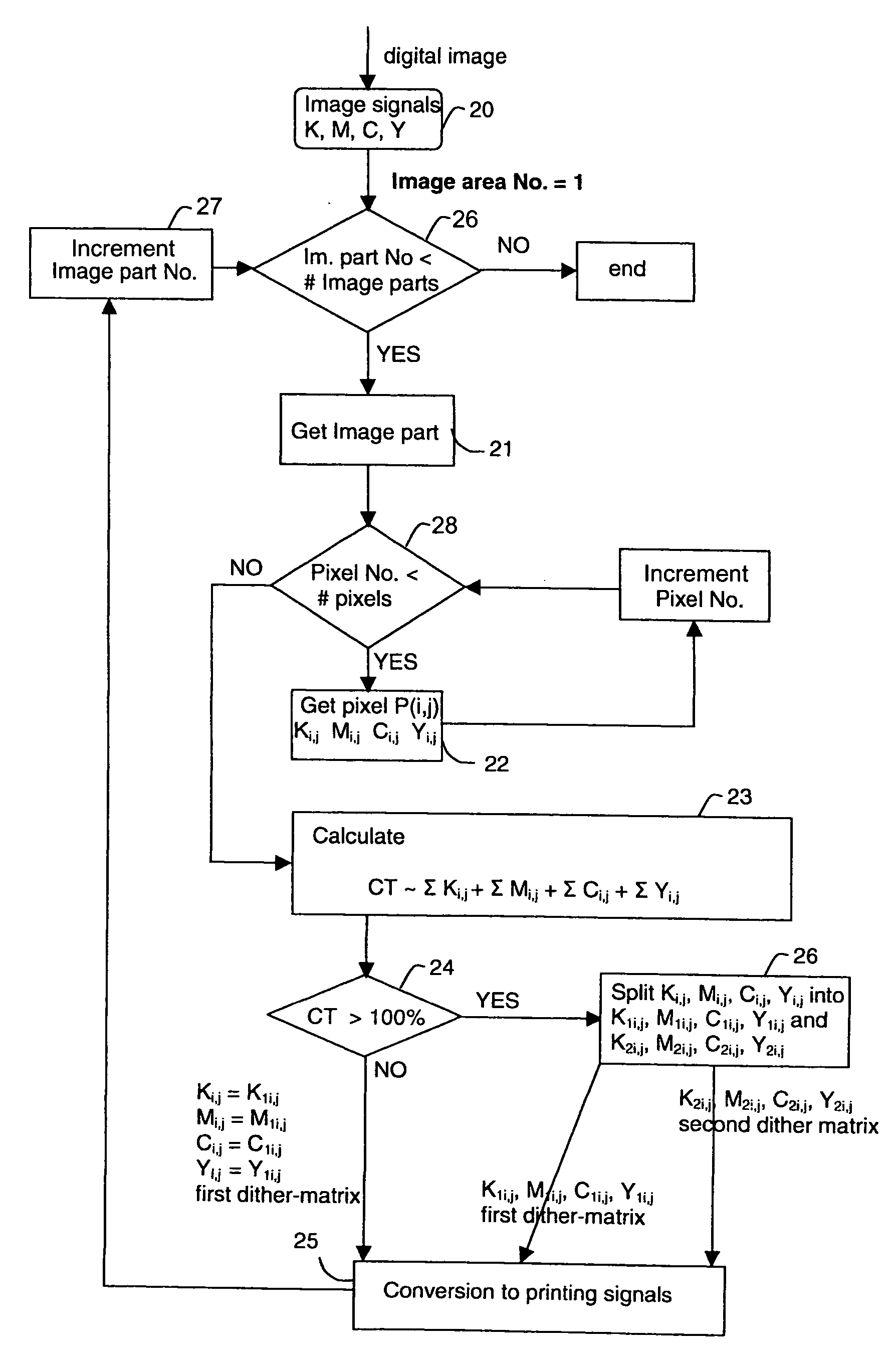
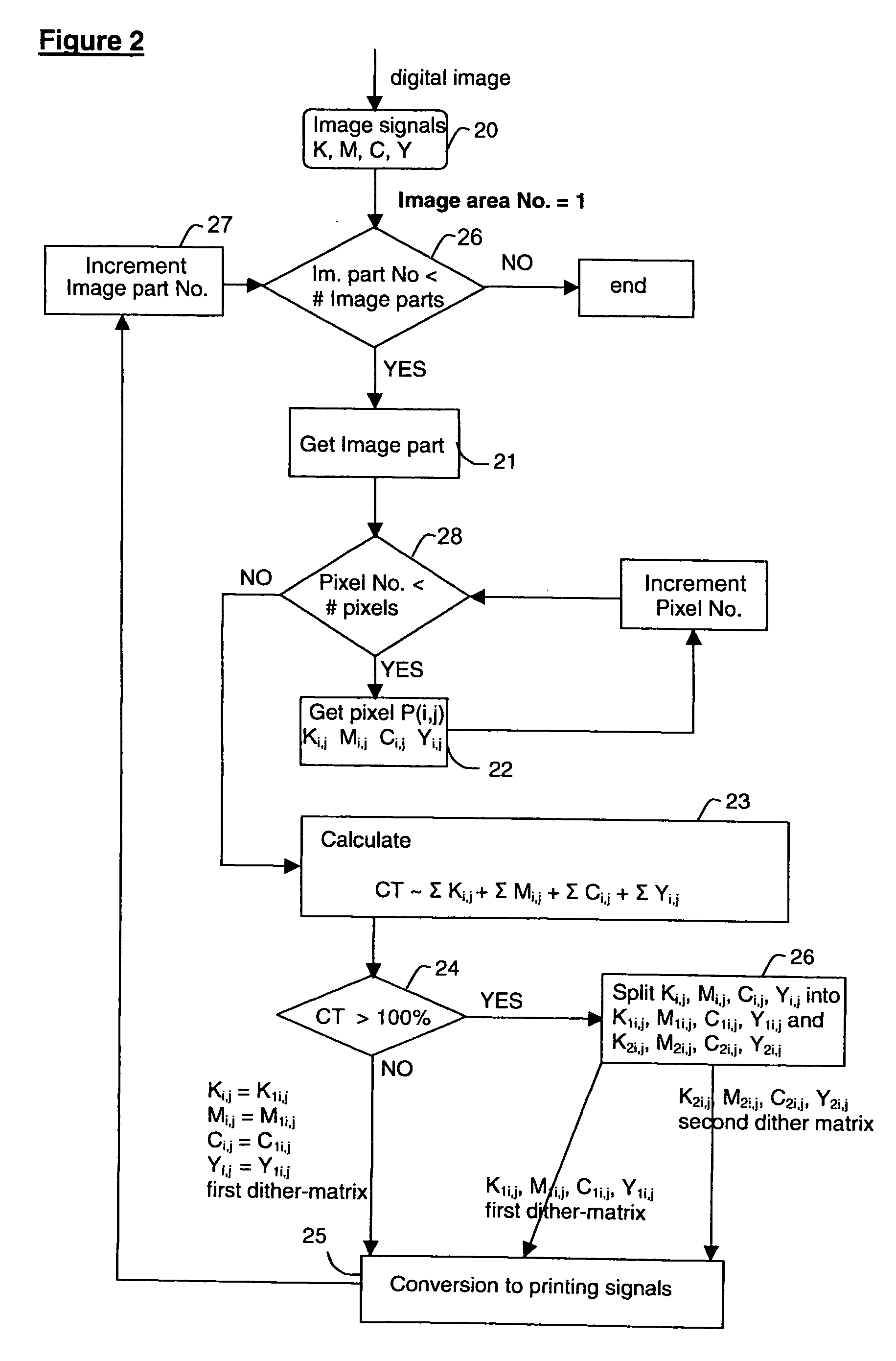
[0016] In an embodiment of the invention, at least two process colours have non-zero second image density values. In the latter case, the method may further comprise the steps of determining a first area coverage fraction of a first process colour of the at least two process colours based on the associated first image density values, and a second area coverage fraction of the first process colour based on the associated second image density values, and a first area coverage fraction of a second process colour of the at least two process colours based on the associated first image density values, and a second area coverage fraction of the second process colour based on the associated second image density values, wherein the dividing is such that the ratio between the first area coverage fraction of the first process colour and the first area coverage fraction of the second process colour differs less than 5% from the ratio between the second area coverage fraction of the first process colour and the second area coverage fraction of the second process colour. Minimizing the variation from layer to layer of the ratios between the area coverage fractions values of at least two process colours has a beneficial effect on the colour balance of the reproduced image.

Problems solved by technology

A disadvantage of this approach employing a plurality of different screens is its sensitivity for creating Moir patterns.
Moir patterns are visible distortions in a rendered multi-colour image caused by interference patterns generated by combining halftone screens.
Although it is known that the visible effect of Moir patterns can be reduced by angling the halftone screens using predetermined screen angles, avoiding Moir becomes particularly troublesome in colour printers where four or more process colours can be rendered.
Therefore using a different screen for each process colour is not an option when more than four process colours are available on the colour printer to render a multi-colour image.
Particularly in case the marking particles are toner particles, as the size of toner particles is typically in the micrometer range, this may limit the amount of process colours which may be used to render an image as an increased number of process colours also may increase the maximum marking particles pile height.
Besides the fact that a high total marking particles pile height is noticeable to the customer both visually and palpably, this may also negatively influence medium curl and transport as well as reduce the resistance against external mechanical influences such as scratches and folding.
Moreover, different image compositions, e.g. different density and / or colour composition, may lead to topographic differences on the image-receiving member which reinforce some of the above mentioned disadvantages and reveal additional disadvantages, such as gloss differences between different image parts.
Using the same screen for both layers may cause undesired interference patterns, e.g., patterns caused by registering errors.
As the raster associated with the first layer is different from the raster(s) associated with the second and any following layer, the formation of undesired interference patterns can be limited.

Method used


Image

  • System and method for processing a multi-colour image
  • System and method for processing a multi-colour image
  • System and method for processing a multi-colour image

Examples


Embodiment Construction

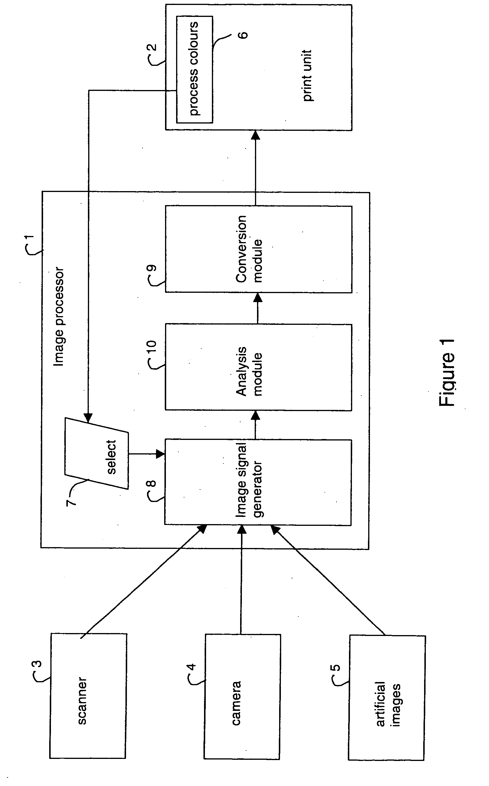
[0049] With reference to the drawings, by means of an example it will be described how a digital multi-colour image can be reproduced employing a halftoning technique according to an embodiment of the present invention. Suppose for instance that an original multi-colour image is scanned at a resolution of 600 dpi.times.600 dpi resulting in a digital multi-colour image being composed of three separation images respectively of the colours red (R), green (G) and blue (B). The image signals associated with the respective separation images specify for each pixel of the respective colour an image density value using an 8-bit representation. An 8-bit representation enables to define 256 levels each corresponding with a particular tonal value. This digital multi-colour image is forwarded to a digital colour printing system. Suppose a selection of 4 process colours is made being black (K), cyan (C), magenta (M) and yellow (Y). The image signal generation module (such as 8 in FIG. 1) of the i...


PUM


Abstract

A system and method are provided for processing digital multi-colour images for the reproduction thereof on a colour printing and / or copying system. Image dots of marking particles of the respective colours associated with the respective colour separation images are positioned contiguous to each other as long as the print area corresponding to the image part to be reproduced is not fully covered so as to create a first layer of marking particles. If the area is fully covered and the image is not yet completely rendered, a second and any following layer of contiguously positioned marking particles is formed on top of the first layer of image dots. The halftoning of the digital image is such that within the same layer all images dots, irrespective of their colour, are obtained using a raster of the same matrix structure, while image dots associated with different layers are obtained using rasters of different matrix structures.

Description

[0001] The present application claims, under 35 U.S.C. .sctn. 119, the priority benefit of European Patent Application No. 02080674.1 filed Dec. 10, 2002, the entire contents of which are herein fully incorporated by reference.[0002] 1. Field of the Invention[0003] The present invention is related to the processing of multi-colour images for reproduction on a printing or copying system. Particularly of interest are systems for forming images composed of a plurality of colour separation images on an image-receiving member wherein the marking particles of the respective colours associated with the respective colour separation images are positioned in superimposed relationship.[0004] 2. Discussion of the Related Art[0005] Marking particles of a limited number of colours, being the process colours, are available on each multi-colour printing system to render a colour image. In digital colour printing, continuous tones are rendered by halftoning the separation images in the process colou...

Claims


Application Information

Patent Timeline
IPC IPC(8): B41J2/52H04N1/405H04N1/46H04N1/52B41J2/525H04N1/60
CPCH04N1/52
Inventor KUIPER, PAUL
Owner OCE TECH
Learn More