
Web material application methods and systems

Active Publication Date: 2004-06-17
ADALIS
View PDF52 Cites 72 Cited by
  • Summary
  • Abstract
  • Description
  • Claims
  • Application Information

AI Technical Summary

Benefits of technology

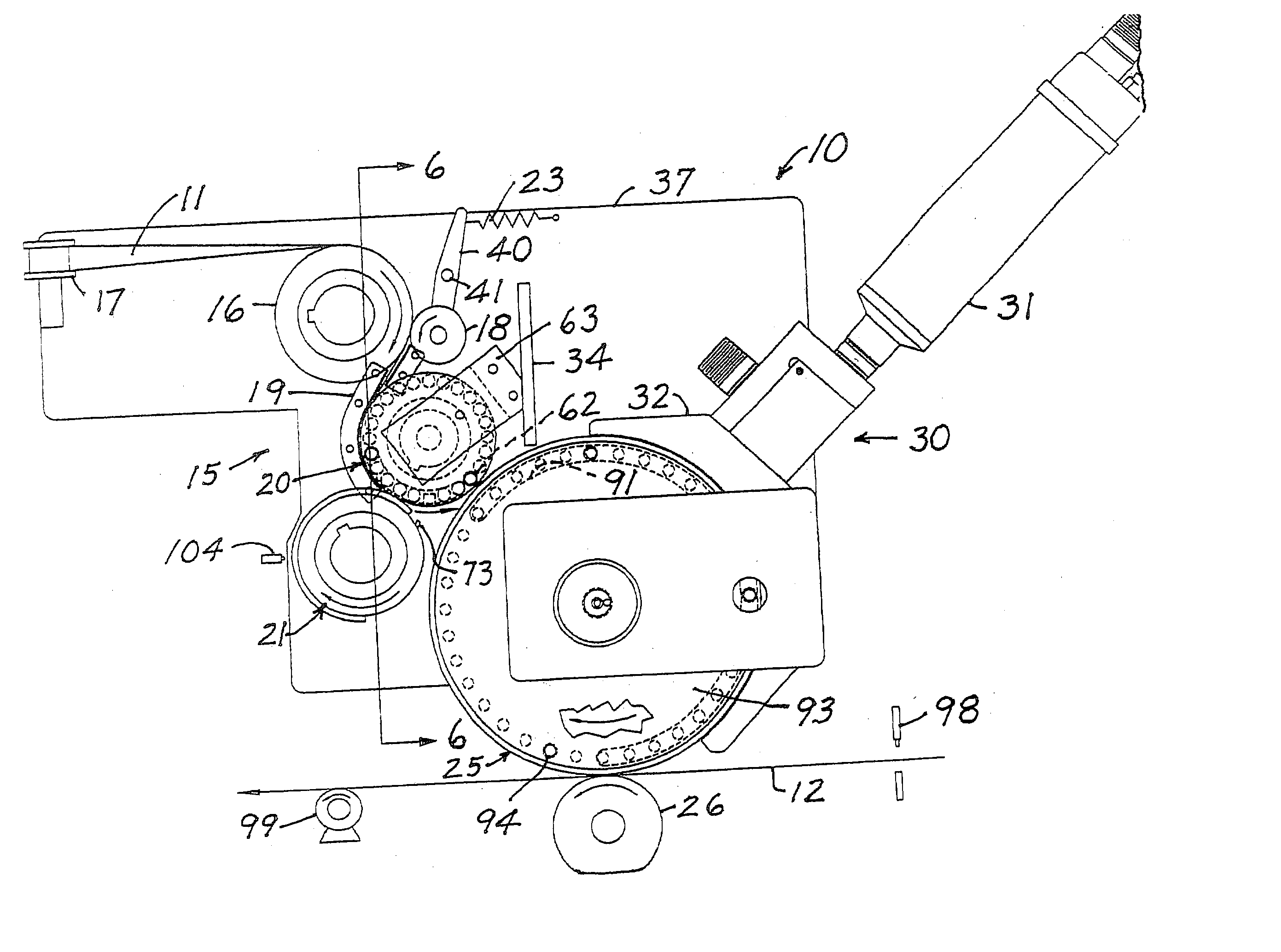
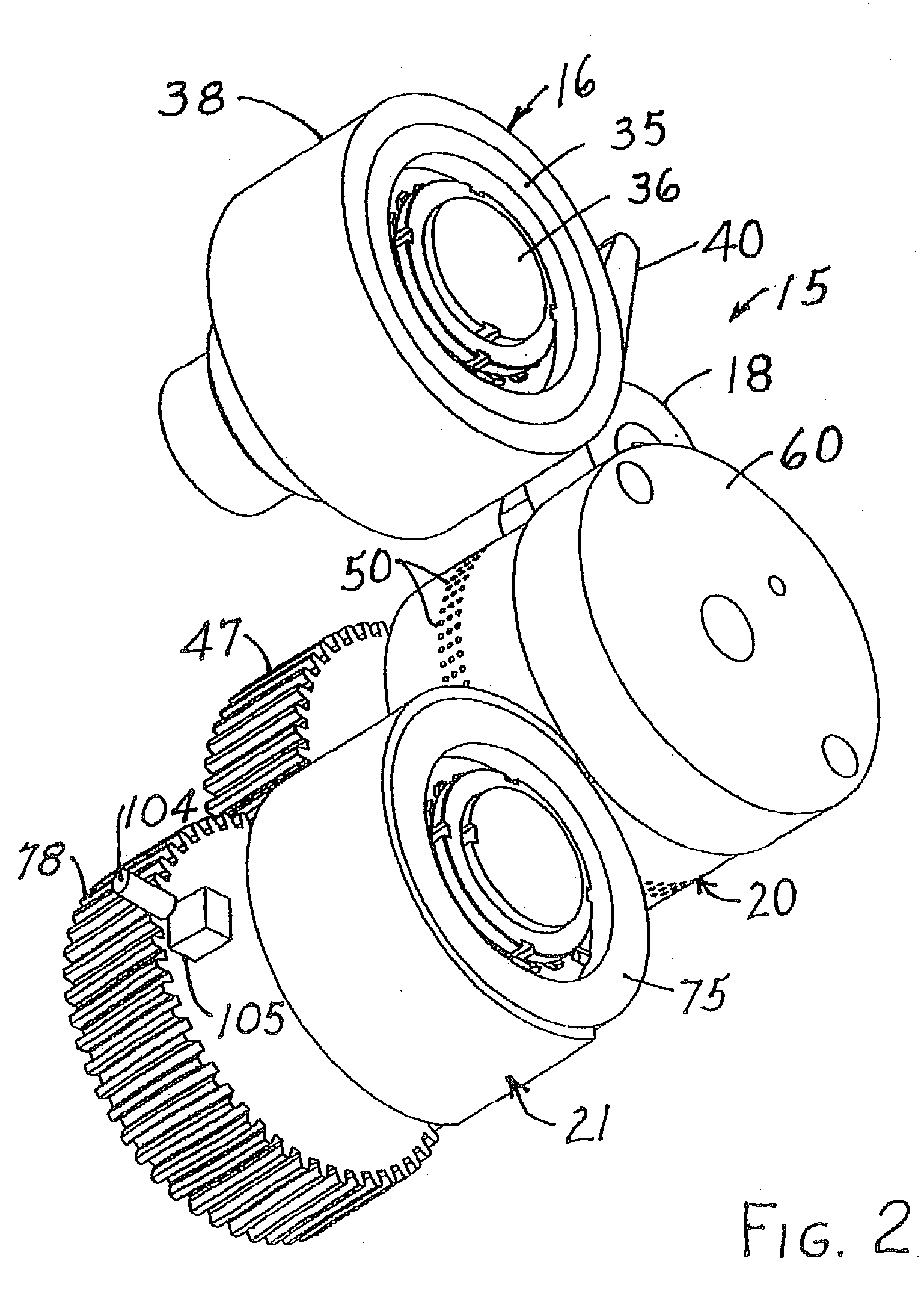
0003] Presently disclosed is a system for applying web material to a substrate. The system may include a feed mechanism configured to advance web material along a predetermined path, and a vacuum roll configured to receive the web material advanced by the feed mechanism. A rotary knife may be positioned near the vacuum roll, and configured to engage the web material in at least one location on the vacuum roll

Problems solved by technology

One recurring problem with such methods and systems is their inability to continuously cut lengths of web material, and then register these cut lengths with a desired location on the substrate as the cut lengths are applied to the substrate.
Another problem is the need to stop production on the systems in order to adjust or reconfigure the system to accept substrates of a different size or shape or to re-position the location of the application of the web material.
A further shortcoming is the difficulty of efficiently operating such systems at high substrate speeds (typically about 600 to about 1000 feet per minute (about 182 meters to about 305 meters per minute).

Method used


Image

  • Web material application methods and systems
  • Web material application methods and systems
  • Web material application methods and systems

Examples


Embodiment Construction

[0018] For ease of understanding, the following terms used herein are described below in more detail:

[0019] "Web material" (which may be used interchangeably herein with "tape") may include, but is not limited to, various ribbon material, various web materials, and various widths of material, particularly tapes with an adhesive such as a hot melt adhesive, a hot melt pressure sensitive adhesive, a hot melt remoistenable adhesive, a water dispersible hot melt adhesive, a biodegradable hot melt adhesive or a repulpable hot melt adhesive, or heat activatable adhesives. Examples of these adhesives are any typical hot melt adhesive such as an ethylene-vinyl acetate copolymer (EVA-based) hot melt adhesive; EMA-based hot melt adhesive (ethylene methylacrylate); EnBA-based hot melt adhesive (ethylene n-butyl acrylate); hot melt adhesive based on polyamides; hot melt remoistenable adhesive based on polyamides and copolyesters; hot melt adhesives based on polyethylene and polypropylene homopo...


PUM

PropertyMeasurementUnit
Timeaaaaaaaaaa
Lengthaaaaaaaaaa
Ratioaaaaaaaaaa

Abstract

Systems and methods for applying a web material to substrates are disclosed. In one example, there is provided a single first drive that may be coupled to a feed mechanism, a vacuum roll, and a rotary knife such that the respective peripheral speed of the feed mechanism, the vacuum roll, and the rotary knife is adjustable to provide a cut web material length that is in registry with a predetermined location on the substrate. In another example, there is disclosed a method that involves detecting a substrate to which a length of web material can be applied, and initiating introduction of a web material into a feed mechanism only if the substrate is detected. Another example includes introducing a web material traveling at a predetermined speed onto a vacuum roll that is positioned near a rotary knife, and rotating the rotary knife at a peripheral speed that is substantially the same as the predetermined speed of the web material traveling on the vacuum roll.

Description

FIELD OF THE DISCLOSURE[0001] The present disclosure relates to methods and systems for applying a web material to a substrate.[0002] There are various methods and systems for applying a web material to a substrate. One recurring problem with such methods and systems is their inability to continuously cut lengths of web material, and then register these cut lengths with a desired location on the substrate as the cut lengths are applied to the substrate. Another problem is the need to stop production on the systems in order to adjust or reconfigure the system to accept substrates of a different size or shape or to re-position the location of the application of the web material. A further shortcoming is the difficulty of efficiently operating such systems at high substrate speeds (typically about 600 to about 1000 feet per minute (about 182 meters to about 305 meters per minute).SUMMARY OF THE DISCLOSURE[0003] Presently disclosed is a system for applying web material to a substrate. T...

Claims


Application Information

Patent Timeline
IPC IPC(8): B65H35/00B65H35/08
CPCB65H35/0013Y10T156/1062B65H35/08B65H2403/21B65H2403/42B65H2403/724B65H2406/33B65H2513/104B65H35/0066Y10T156/133Y10T156/12Y10T156/1075B65H2220/02B65H2220/04B65H2513/10
Inventor GROVES, MATTHEW E.FAIRCHILD, MICHAEL A.
Owner ADALIS
Learn More