
Patient interface with forehead support system

a support system and patient technology, applied in the field of patient interface with forehead support system, can solve the problems of not optimizing the range of positions of the forehead on the human head, the mask may be compressed against the patient,

Active Publication Date: 2004-03-11
RIC INVESTMENTS LLC
View PDF17 Cites 327 Cited by
  • Summary
  • Abstract
  • Description
  • Claims
  • Application Information

AI Technical Summary

Benefits of technology

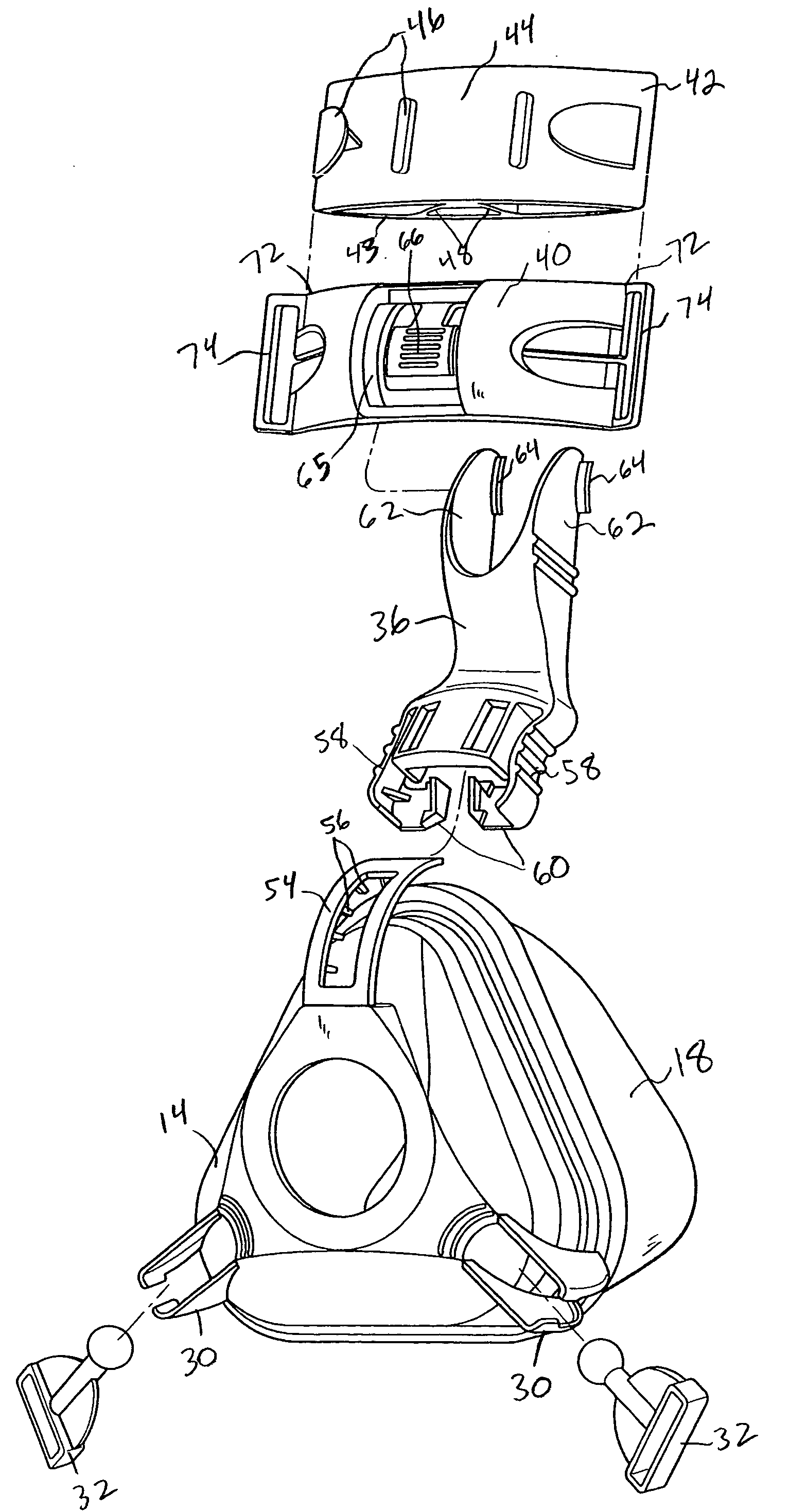
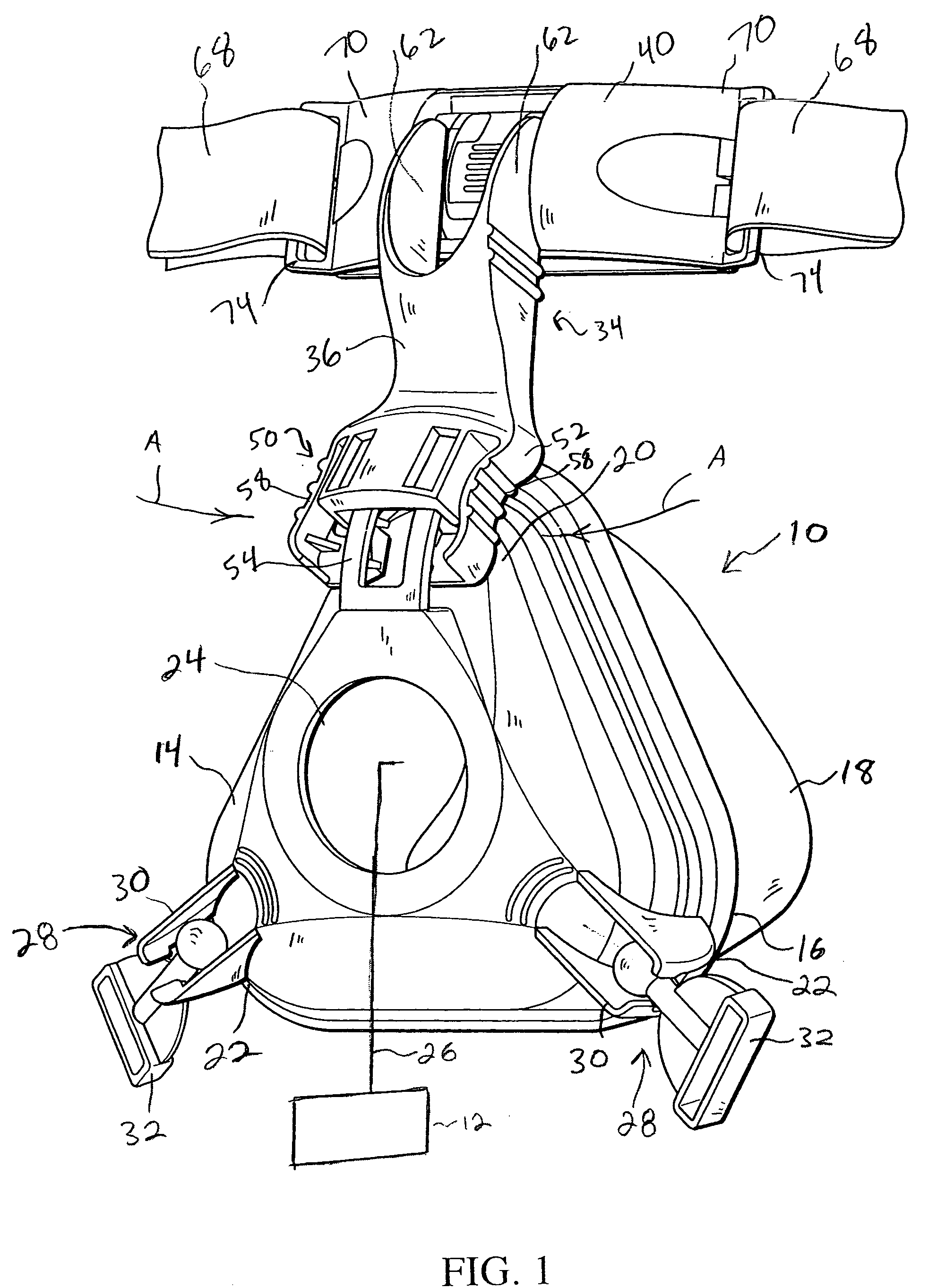
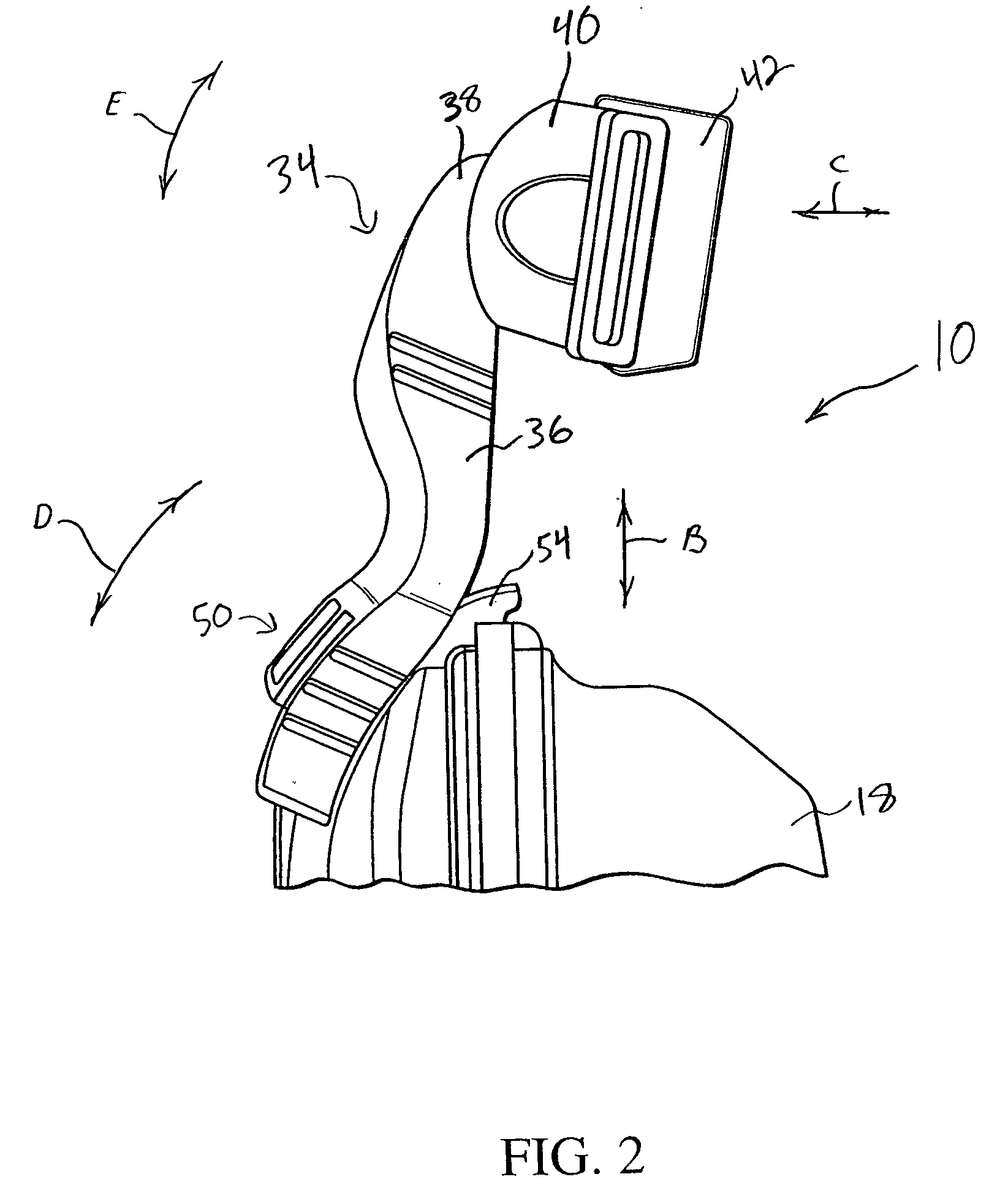
[0012] An exemplary embodiment of the present invention includes a forehead support bracket which is slideably connected to the support arm. The forehead support bracket is self-aligning so that it allows the forehead pad to remain parallel to the patient's forehead at all times, thus enhancing comfort and stability. In an exemplary embodiment of the present invention, the forehead support bracket is removable from the support arm, allowing the headgear (with forehead support bracket attached) to be donned separately from the mask and support arm. This allows the patient to easily remove the mask without having to remove the headgear straps. An exemplary embodiment of the present invention further comprises a forehead support bracket having a forehead pad formed from the headgear itself.

Problems solved by technology

A problem arises in that in order for the mask to maintain a seal without any undue gas leaks around the periphery of the mask, the mask may be compressed against the patient's face.
While pivotal movement of the cushion frame to the joining member in one dimension allows the position of the forehead cushions to be adjusted, it does not optimize the ranges of positions for the forehead on a human head.

Method used


Image

  • Patient interface with forehead support system
  • Patient interface with forehead support system
  • Patient interface with forehead support system

Examples


second embodiment

[0043] FIGS. 4-6 illustrate alternative embodiments for the adjustment assembly for the support arm of the forehead support. In a second embodiment illustrated in FIG. 4, adjustment assembly 50' of the present invention includes forming support arm 36' into two portions: a shell portion 76 connected to mask shell 14', and a bracket portion 78 connected to forehead support bracket 40'. The portions are connected to each other using a ratchet-type connection. Shell portion 76 has a generally tubular cross section having an exterior guide slot 80 having opposed ratchet-like teeth 82. The bracket portion 78 also has a generally tubular cross section adapted to slide within the shell portion 76 and having a central protrusion 84 corresponding to the guide slot 80. It is to be understood, however, that the present invention contemplates reversing the orientation of the tubular shell portion and the bracket portion, so that shell portion with the tubular slot is provided on the forehead su...

fifth embodiment

[0046] In the fifth embodiment illustrated in FIGS. 7-12, the forehead support comprises a support arm 36"" which is pivotally attached to a horizontal forehead support bracket 40"" by means of a coupling system generally indicated at 91. Mask shell 14"" further includes an adjustment assembly 50"" adjustably connecting the support arm 36"" to mask shell 14"". Mask shell 14"" includes an arcuate attaching member 54' rigidly attached to and extending from a central portion of mask shell 14"" above inlet opening 24' to upper apex 20'. Attaching member 54' includes two concentrically arched ribs 90 forming a slot 92 therebetween. The outer curved portion includes a series of horizontal teeth and alternating grooves 94.

[0047] Support arm 36"" includes a pair of arched engaging elements 96 (FIG. 9) that slide within the slot 92 on the attaching member 54'. A locking assembly 98 is provided to latch support arm 36"" to attaching member 54'. In the illustrated embodiment, locking assembly ...


PUM


Abstract

A patient interface having a forehead support adjustably. The forehead support assembly includes a support arm that is adjustably mounted to the mask shell, thereby allowing the adjustment of the distance between the forehead support bracket and the mask shell in order to adjust for patient's of different sizes. A forehead support bracket is pivotally connected to the support arm. The pivoting forehead support bracket is self-aligning to allow the forehead pad to remain parallel to the patient's forehead at all times, thus enhancing comfort and stability. The forehead support bracket is removable from the support arm, allowing the headgear (with support bracket attached) to be donned separately from the mask and support arm. The forehead support bracket in one embodiment has a forehead pad formed from the headgear itself.

Description

[0001] This application claims priority under 35 U.S.C. .sctn. 119(e) from provisional U.S. patent application No. 60 / 408,836 filed Sep. 6, 2002, the contents of which are incorporated herein by reference.[0002] 1. Field of the Invention[0003] The present invention pertains to a support system for a gas delivery mask, and, in particular to a forehead support system for a gas delivery mask and to a system for supplying a flow of gas to a patient that incorporates such a forehead support system.[0004] 2. Description of the Related Art[0005] There are numerous situations where it is necessary or desirable to deliver a flow of breathing gas non-invasively to the airway of a patient, i.e., without intubating the patient or surgically inserting a tracheal tube in their esophagus. For example, it is known to ventilate a patient using a technique known as non-invasive ventilation. It is also known to deliver continuous positive airway pressure (CPAP) or variable airway pressure, which varie...

Claims


Application Information

Patent Timeline
Patent Type & Authority Applications(United States)
IPC IPC(8): A61HA61M16/00A61M16/06A62B18/02A62B18/08
CPCA61M16/06A61M16/0683Y10T403/32245A61M16/0638A61M16/0633A61M16/0655
Inventor EATON, JASON P.LORDO, RICHARD J.BUSCH, LANCEHO, PETER
Owner RIC INVESTMENTS LLC
Learn More