
Plews impulse drive

a technology of impulse drive and cylinder, which is applied in the direction of belts/chains/gearings, motors, belts/chains/gearings, etc., can solve the problems of increasing power loss of automatic transmission, consuming significant amounts of engine/motor output of torque converters, and energy inefficiencies, so as to reduce production costs, facilitate and efficiently manufacture and market, the effect of increasing energy efficiency

Inactive Publication Date: 2004-02-26
PLEWS DENNIS J
View PDF0 Cites 8 Cited by
  • Summary
  • Abstract
  • Description
  • Claims
  • Application Information

AI Technical Summary

Benefits of technology

[0018] Energy to rotate the movable masses and actuate the mass accelerators is externally supplied, thus complying with the conservation of energy laws. The mass accelerators may easily be powered by commercially available hydraulic pumps, pistons and valves, which themselves are powered by commonly available electric motors or fossil fuel engines. In the version described herein it is contemplated that a single, external source us used to provide all needed power to the invention. The mass accelerators can be computer controlled to fit the performance needs of the operator. Since the mass accelerators may be positioned anywhere to intercept the motion of the thrust masses about the periphery of their circular motion, the thrust vector produced can be varied at the direction of the operator. Since there are few moving parts that move against other component parts, friction is minimized. As the thrust that is produced by the invention can cause any device to which the invention is attached to move, such as motor vehicles, boats and aircraft, without any need for additional devices, the inherent inefficiencies of automotive drive trains and propellers are avoided, thus markedly improving fuel efficiency throughout the transportation industry. Since the device is significantly less massive than passenger vehicle's transmission and drive train, substantial weight savings are achieved with the added benefit of further increasing fuel efficiency.
[0022] It is therefore an object of the present invention to reduce power loss and increase energy efficiency when converting the energy generated by the engine / motor into linear motion.
[0024] It is an object of the present invention to provide an impulse drive that may be easily and efficiently manufactured and marketed.
[0026] Another object of the present invention is to provide economic benefits resulting from the reduced cost of production of the invention as compared to the cost of the production of automotive drive trains.
[0027] Still another object of the present invention is to reduce the cost of automobiles to the consumer due to the reduced production cost of motor vehicles that utilize the invention.

Problems solved by technology

Each of these technologies suffer significant power losses, and resulting energy inefficiencies, when using current technologies for converting the angular momentum generated by the engine / motor.
There is more power loss with an automatic transmission than there is with a manual transmission as the power to actuate the internal clutches and shift the gears comes from the engine / motor.
The torque converter also consumes significant amounts of the engine / motor output which is radiated away as heat.
Ideally, though, the transmission would move at exactly the same speed as the engine, because this difference in speed wastes power.
Jet engine efficiency similarly suffers losses between the input of the fuel's energy and the output of the thrust energy.
Moreover, propeller aircraft suffer significant efficiency losses as altitude increases.
Marine propellers have thrust to input power ratios similar to aircraft propellers with the additional problem of corrosion and encrustation thrust losses not suffered by aircraft propellers.

Method used


Image

  • Plews impulse drive
  • Plews impulse drive
  • Plews impulse drive

Examples


Embodiment Construction

:

[0040] The impulse device 10 of the present invention represents a significant advance over the current methods used by transportation technologies to convert the rotational energy generated by an engine or motor into linear motion. The invention is intended to replace existing automotive transmissons and drive train assemblies and aeronautical and marine propellers.

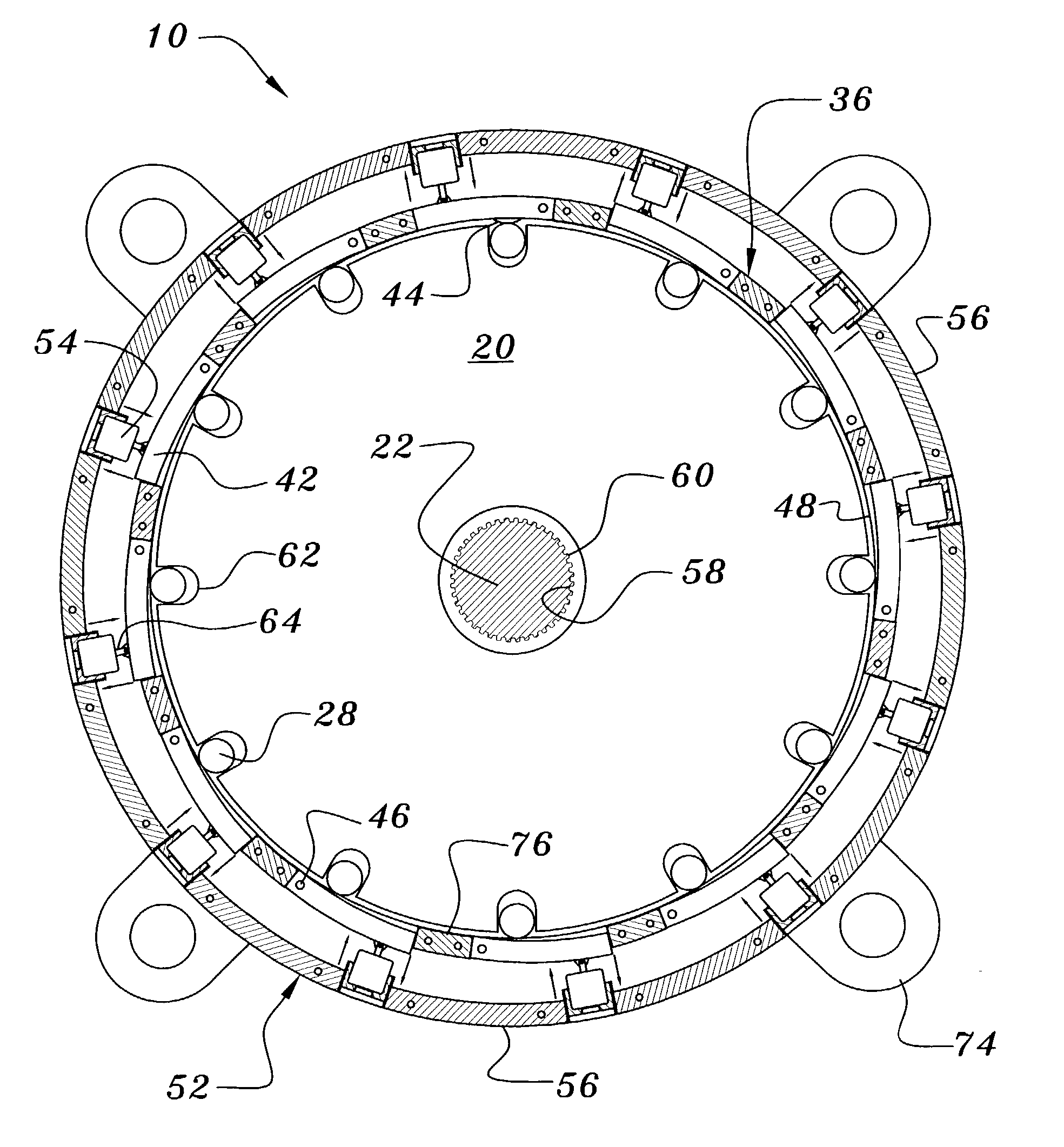
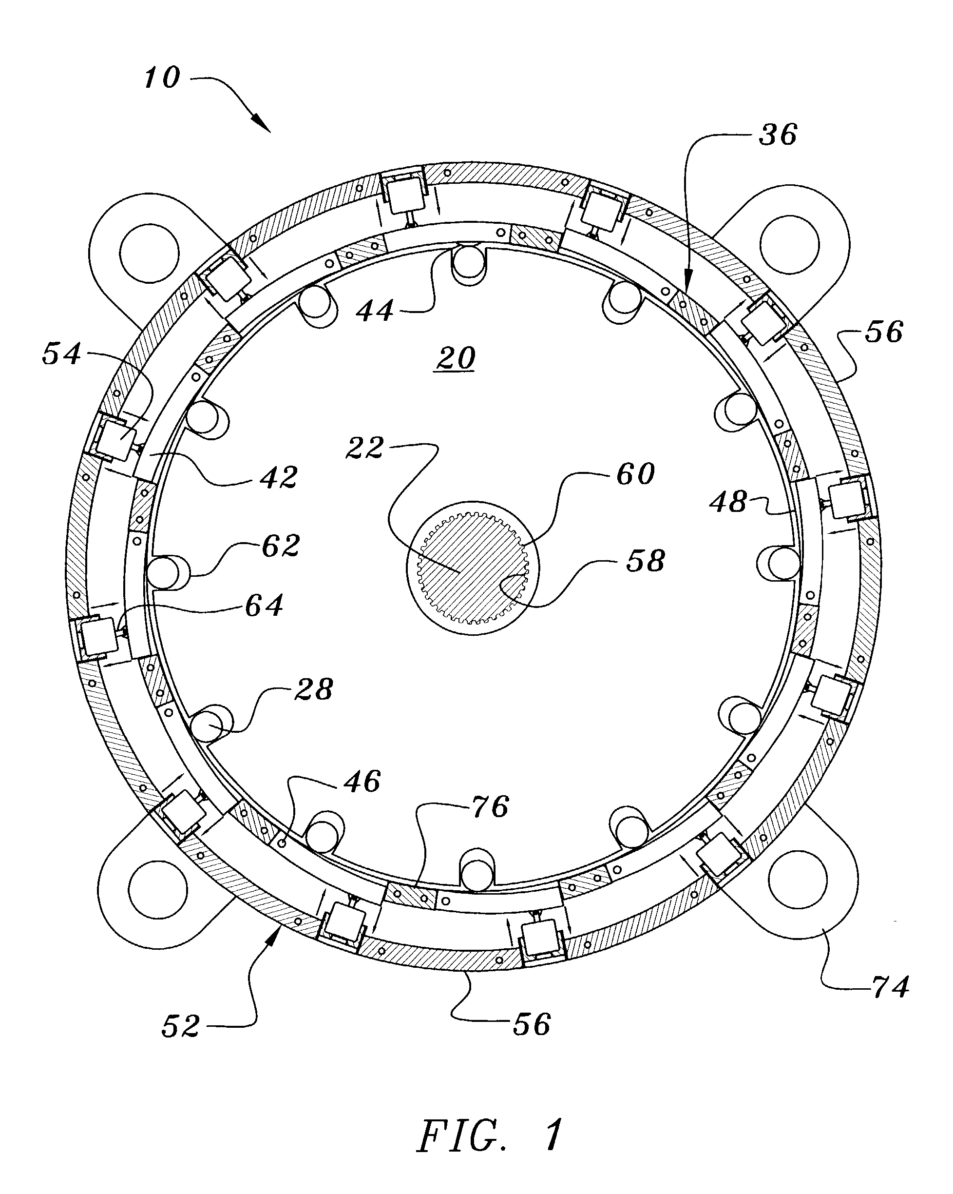
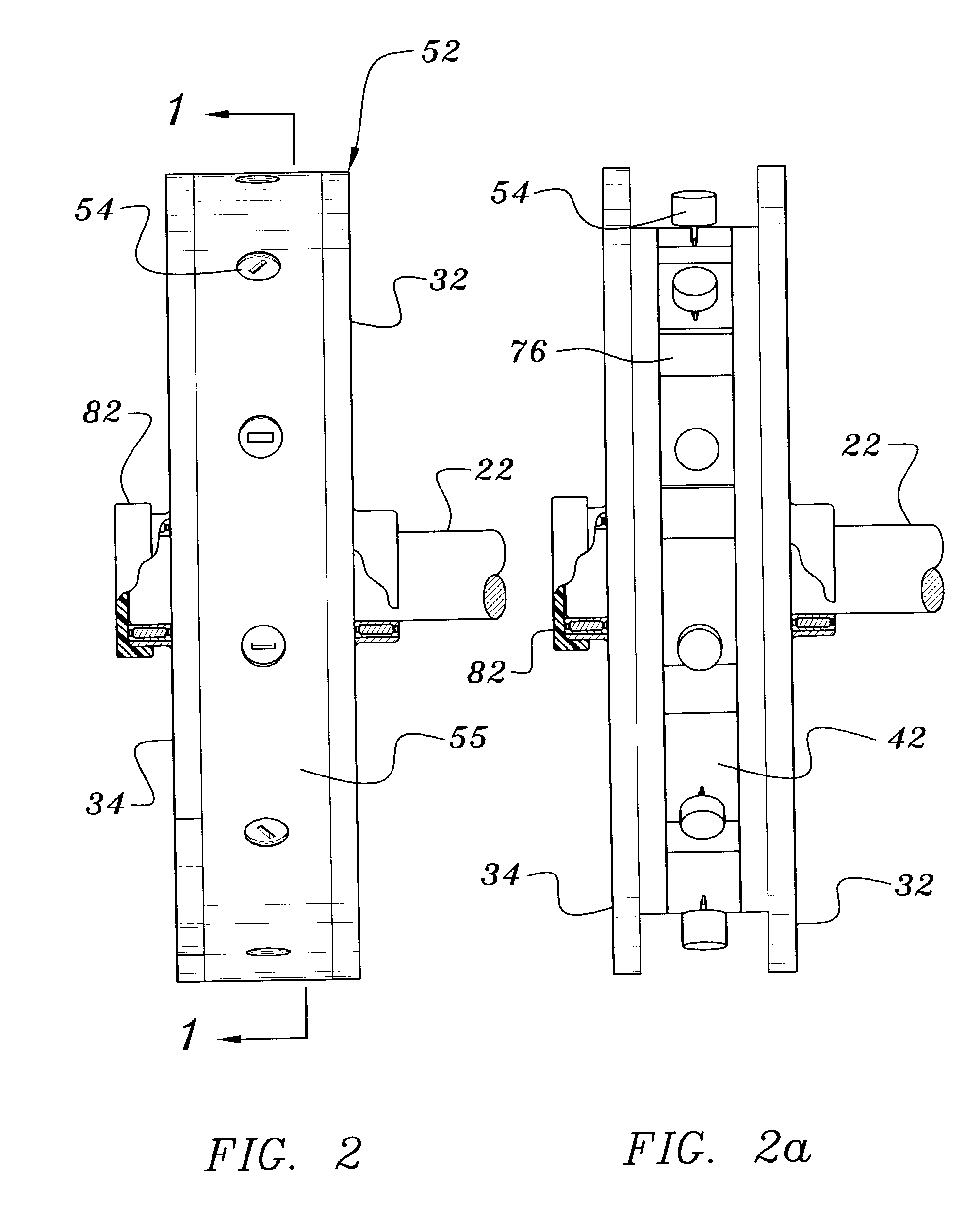
[0041] Specifically, as partially shown in FIGS. 1 and 2, the invention consists of a circular disk 20, a main rotational axle drive shaft 22 onto which the circular disk is mounted and through which rotational energy is provided by connecting the drive axle shaft to an external engine or motor 26 by currently used methods, multiple movable cylindrical masses 28, two circular bearing rings 32 and 34 that sandwich a centrally positioned inner circular bearing ring 36 made of individual, movable bearing arc segments 42 that have acceleration humps 44 on the internally facing surface and each one is fixed at one end by a p...


PUM


Abstract

An impulse drive for converting inertial and rotational energy into linear motion includes a pair of thrust mass bearing race, with one of the pair of thrust mass bearing race attached to the interior of the top circular bearing ring and another of the pair of thrust mass bearing race attached to the interior of the bottom circular bearing ring, an inner circular bearing ring is coupled to the pair of thrust bass bearing race and have movable arc segments that move into and away from the path of thrust mass that move radially freely within cavities of a rotating circular disk, the rotating circular disk is moved by a axle drive that varies the rotational velocity of the disk, a mass accelerator girdle is positioned exterior the inner circular bearing ring and coupled to the interior of the top and bottom circular bearing rings, with mass accelerators fastened into the mass accelerator girdle and positioned over pistons of the movable arc segments in such a fashion that the amount of force needed to accelerate the trust masses, and the resulting thrust generated by the device is contained and controlled.

Description

[0001] 1. Field of Invention:[0002] The present invention relates to an impulse device and more particularly pertains to mounting freely movable masses about the periphery of a circular disk which is in turn mounted onto a main rotational axis drive shaft, whereby energy is provided to cause the circular disk to rotate at high speeds, while having the ability to move the freely movable masses radially toward and away from the axis of rotation. The invention further relates to a new method of converting inertial and rotational energy, as generated by an engine or motor, into linear motion.[0003] 2. Description of the Related Art:[0004] Current transportation technologies use a variety of mechanisms to convert the rotational energy generated by the engine or motor contained within the vehicle into the linear motion of the vehicle. In the automotive world there are three basic forms of the mechanical device generally known as a transmission that is connected to the motor / engine and in ...

Claims


Application Information

Patent Timeline
Patent Type & Authority Applications(United States)
IPC IPC(8): F03G3/00
CPCY10T74/18536F03G3/00
Inventor PLEWS, DENNIS J.
Owner PLEWS DENNIS J
Learn More