Rail structure for the door

a rail structure and door technology, applied in the field of rail structure for doors, can solve the problems of large replacement task, high cost, and inadequacies of doors with this type of rail structur

Inactive Publication Date: 2004-02-05
NIPPON JIDO DOOR
View PDF11 Cites 16 Cited by
  • Summary
  • Abstract
  • Description
  • Claims
  • Application Information

AI Technical Summary

Benefits of technology

[0007] As explained above, by the invention according to the first aspect, by dividing the track rail into the track rail body and the load support member, and by replaceably attaching the track rail body to the load support member, because the replacement of only the track rail body becomes possible, the replacement of the load support member becomes unnecessary, the replacing operation of the track rail body in the case in which it is worn becomes easy, and the cost for replacement is decreased. Furthermore, by separating the load support member and the track rail body, both can respectively be made of different materials, and it is possible to choose a suitable material for each function.
[0021] By the invention according to the eighth aspects, by forming the concave part and the convex part, both of which are engaged with each other on the upper surface of the track rail body and the outer surface of the wheels of the door, the derailing of the wheels from the track rail body can be prevented. Particularly in the invention according to the seventh aspect, because the convex part is formed on the upper surface of the track rail body, the leaning backward of the track rail toward the continuing direction can be restricted.

Problems solved by technology

However, regarding the above-mentioned conventional rails for doors, in the case that the track rail body which directly contacts the door wheels need be replaced, because the entire track rail including load support member must be replaced, there were disadvantages not only in that the replacement task became large-scaled, but also in that the cost for the replacement was also high.
There was also a disadvantage in that doors with this type of rail structure are not appropriate for use, particularly in wards where the quietude is required such as hospitals, residential areas, offices, etc., because vibrations made by the running of the door wheels are directly transmitted through to the building.

Method used


Image

  • Rail structure for the door
  • Rail structure for the door
  • Rail structure for the door

Examples


first embodiment

[0029] First Embodiment

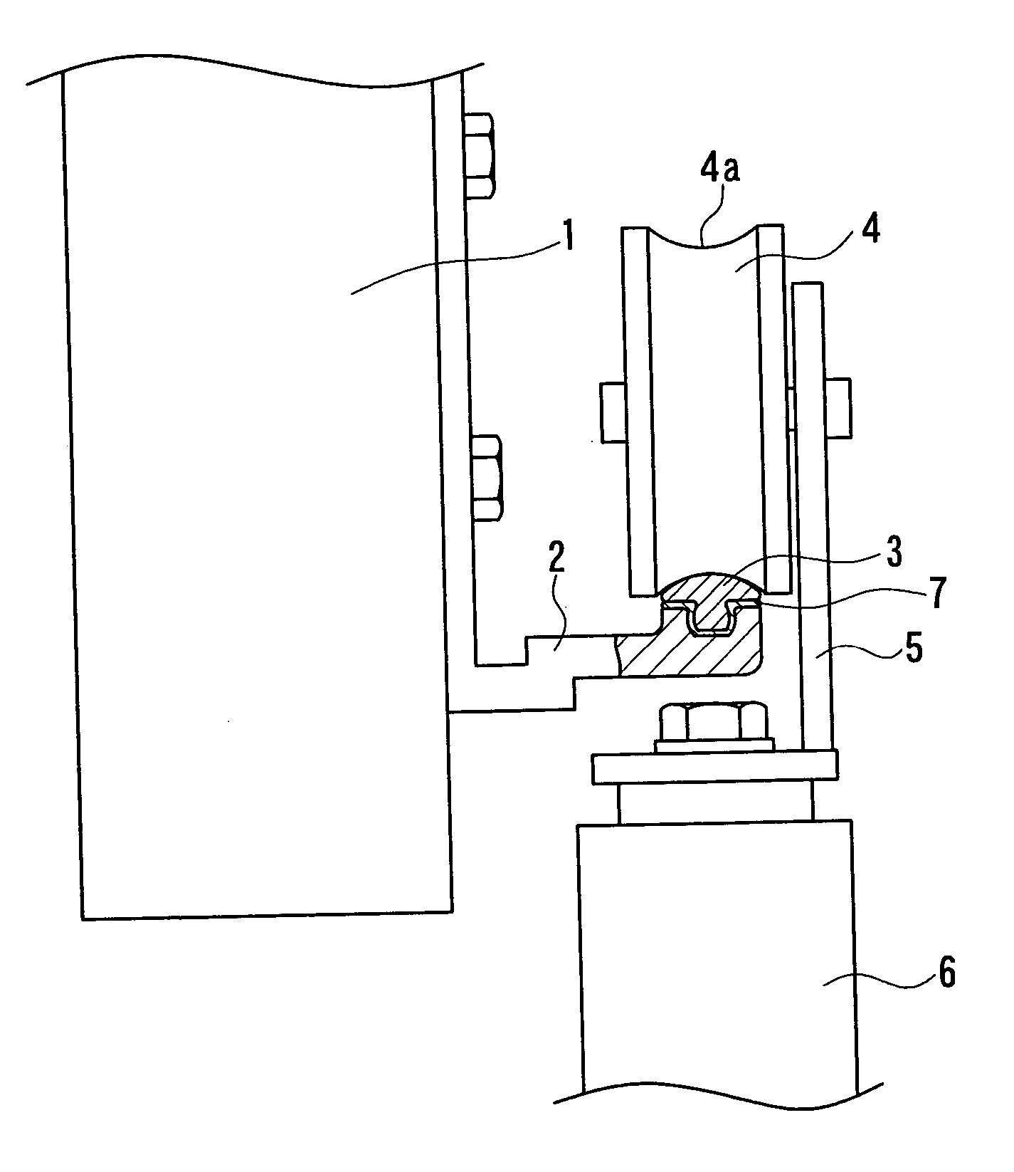
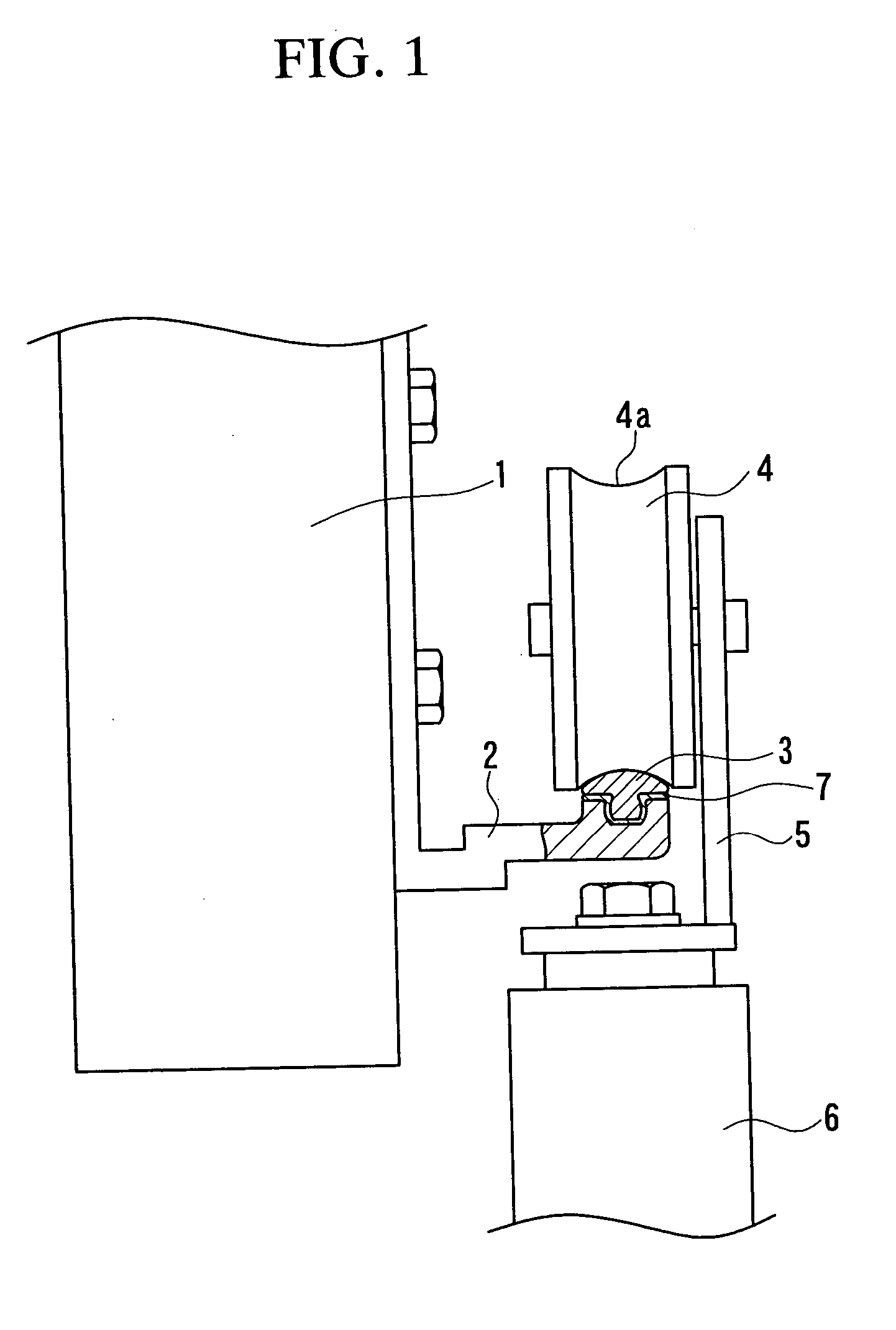
[0030] First preferred embodiment of the rail structure according to the present invention will be explained with reference to FIG. 1 and FIG. 2. FIG. 1 shows the state in which load support member 2 is installed on member of building side 1, the track rail body 3 is fit to this load support member 2, door wheels 4 are engaged onto the upper surface of this track rail body 3, door wheels 4 freely roll on the upper surface of this track rail body 3, and the door 6 is suspended from the door wheels 4 via brackets 5. Plural door wheels 4 are engaged with the track rail body 3 in the longitudinal direction of the track rail body 3, and door 6 is suspended from the track rail body 3 by these door wheels 4, and door 6 freely runs on the track rail body 3.

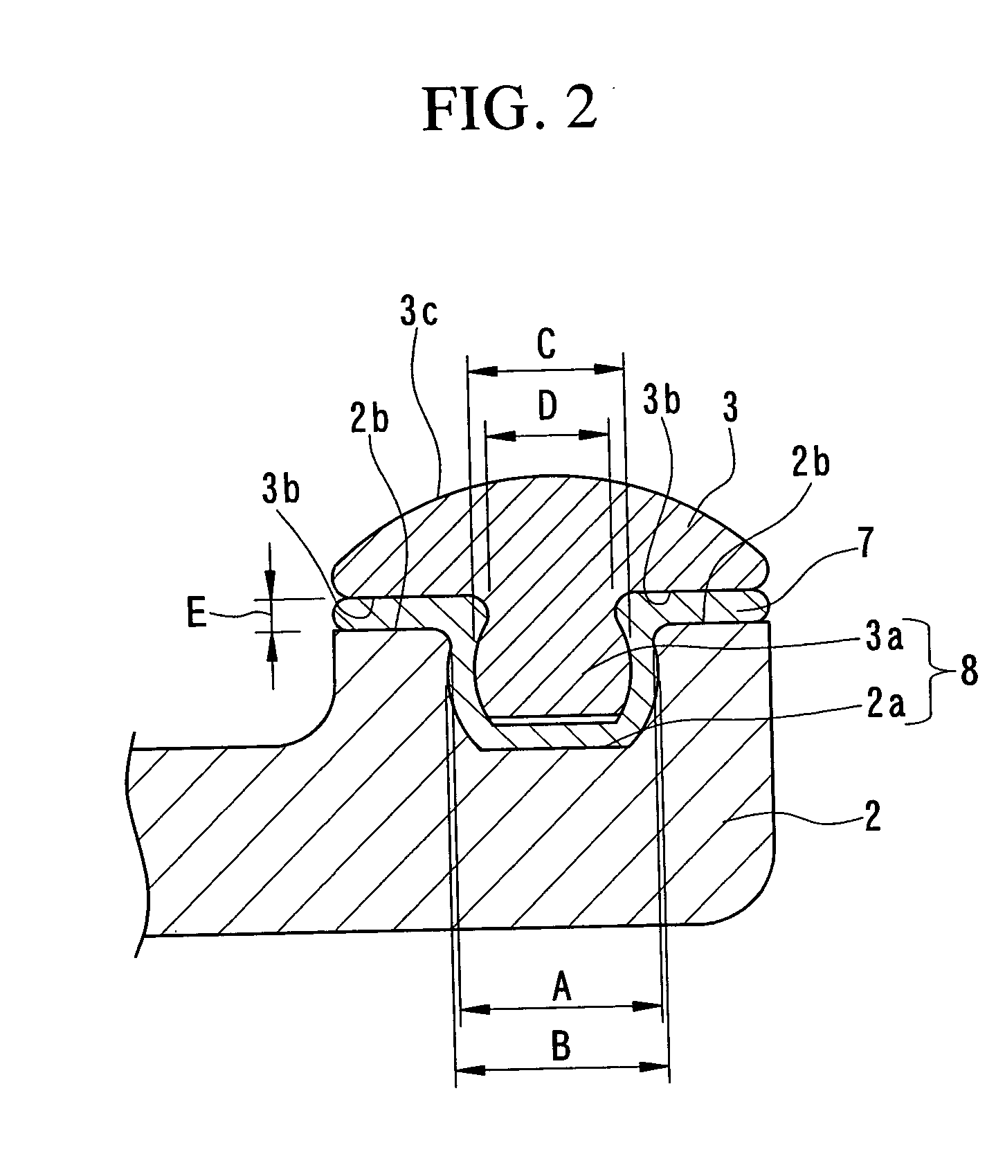
[0031] FIG. 2 is a partial enlarged cross section of FIG. 1, wherein cushion member 7 is placed between the load support member 2 and the track rail body 3. The cushion member 7 is a board-shaped material having an ...

second embodiment

[0042] Second Embodiment

[0043] Next, the second preferred embodiment of the rail structure for doors according to the present invention will be explained with reference to the drawings FIG. 3 and FIG. 4. The fact that the rail structure of the second preferred embodiment differs from that of the first preferred embodiment is only in the shape of the wheels and the shape of the track rail body; other structures and the relationships of the dimensions of each part are the same as in the first preferred embodiment, and therefore, identical reference numerals are attached to the identical parts, and the explanation thereof is omitted.

[0044] The convexo-concave shape of an engaged part of the door wheels 4 of the door 6 and the track rail body 3 in the second preferred embodiment is in opposite relationship to the convexo-concave shape of the engaged part in the first preferred embodiment. To explain in more detail, while in the first preferred embodiment, the upper surface of the track ...


PUM

PropertyMeasurementUnit
Dimensionaaaaaaaaaa
Hardnessaaaaaaaaaa

Abstract

A rail structure for doors comprises a track rail body (3) which supports the door wheels (4) which are attached to a door (6) and freely roll on the track rail body (3), a load support member (2) which is extended along the track rail body (3) and supports the track rail body (3) from the bottom side, a cushion member (7) which is disposed between the track rail body (3) and the load support member (2) and absorbs the vibration from the track rail body (3). A convexo-concave fitting part (8) which performs convexo-concave fitting is formed on the bottom surface of the track rail body (3) and on the upper surface of the load support member (2) via the cushion member (7). Purposes of the invention are to prevent vibrations caused by the running of the door wheels (4) from being transmitted to building, and to improve the efficiency of replacement operations for the track rail body (3), and to lower the cost.

Description

[0001] The present invention relates to a door rail structure for automatic doors and for other types of doors.[0002] In conventional rails for doors, the track rail body on which the door wheels run and the load support member which attaches the rail body to a building are formed in a single piece, and these rails were installed in the buildings via this load support member by engaging devices such as bolts. These rails for doors are made of material which is harder than materials for wheels of the doors to avoid wear, and generally, extruded aluminum materials and steel materials are used.[0003] However, regarding the above-mentioned conventional rails for doors, in the case that the track rail body which directly contacts the door wheels need be replaced, because the entire track rail including load support member must be replaced, there were disadvantages not only in that the replacement task became large-scaled, but also in that the cost for the replacement was also high.[0004]...

Claims


Application Information

Patent Timeline
IPC IPC(8): E05D15/06
CPCE05D15/0652E05Y2201/684E05Y2800/205E05Y2900/132E05Y2800/20Y10T16/3825E05Y2800/678Y10T16/373Y10T16/379Y10T16/381E05Y2800/27E05Y2800/422
Inventor KOIKE, KATSUFUMI
Owner NIPPON JIDO DOOR
Why Eureka
Try Eureka