
Airbag trigger control system

a technology of airbag trigger and control system, which is applied in the direction of vehicle components, pedestrian/occupant safety arrangements, vehicular safety arrangments, etc., can solve the problem of not being able to determine the abnormal state of satellite sensors

Inactive Publication Date: 2004-01-15
TOYOTA JIDOSHA KK
View PDF3 Cites 20 Cited by
  • Summary
  • Abstract
  • Description
  • Claims
  • Application Information

AI Technical Summary

Benefits of technology

[0011] The second sensor generates a signal corresponding to the impact exerted to the vehicle and also generates a predetermined signal at a predetermined interval. When a predetermined signal of the second sensor is not detected in a predetermined number of successive control cycles or for a predetermined period of time, the predetermined threshold value for triggering the airbag is changed to a given value as the threshold value. This makes it possible to reliably change the predetermined threshold value for triggering the airbag system to the given value as the threshold value for abnormal conditions, even in the state where the output signal of the second sensor becomes unavailable owing to such conditions, for example, when the second sensor becomes incapable of generating a signal representing abnormality thereof, and when the output signal generated from the second sensor corresponding to the impact exerted to the vehicle body cannot be detected due to disconnection of the signal line connecting between the second sensor and the electronic control unit, or the like.
[0015] According to the invention, it is determined whether the detected output signal of the second sensor has abnormality each time the output signal is detected. When the output signal of the second sensor is not detected in a predetermined number of successive control cycles or for a predetermined period of time, the predetermined threshold value for the airbag trigger control is changed to the given value. This arrangement makes it possible to reliably change the predetermined threshold value for triggering the airbag to the given value on condition that the output signal of the second sensor is unavailable or has abnormality, e.g., the output signal of the second sensor takes an unusual form that cannot be identified as the signal corresponding to the impact exerted to the vehicle.

Problems solved by technology

In the aforementioned conditions, however, it is not possible to determine the abnormal state of the satellite sensors on the basis of the abnormality determination signals generated thereby.

Method used


Image

  • Airbag trigger control system
  • Airbag trigger control system
  • Airbag trigger control system

Examples


Embodiment Construction

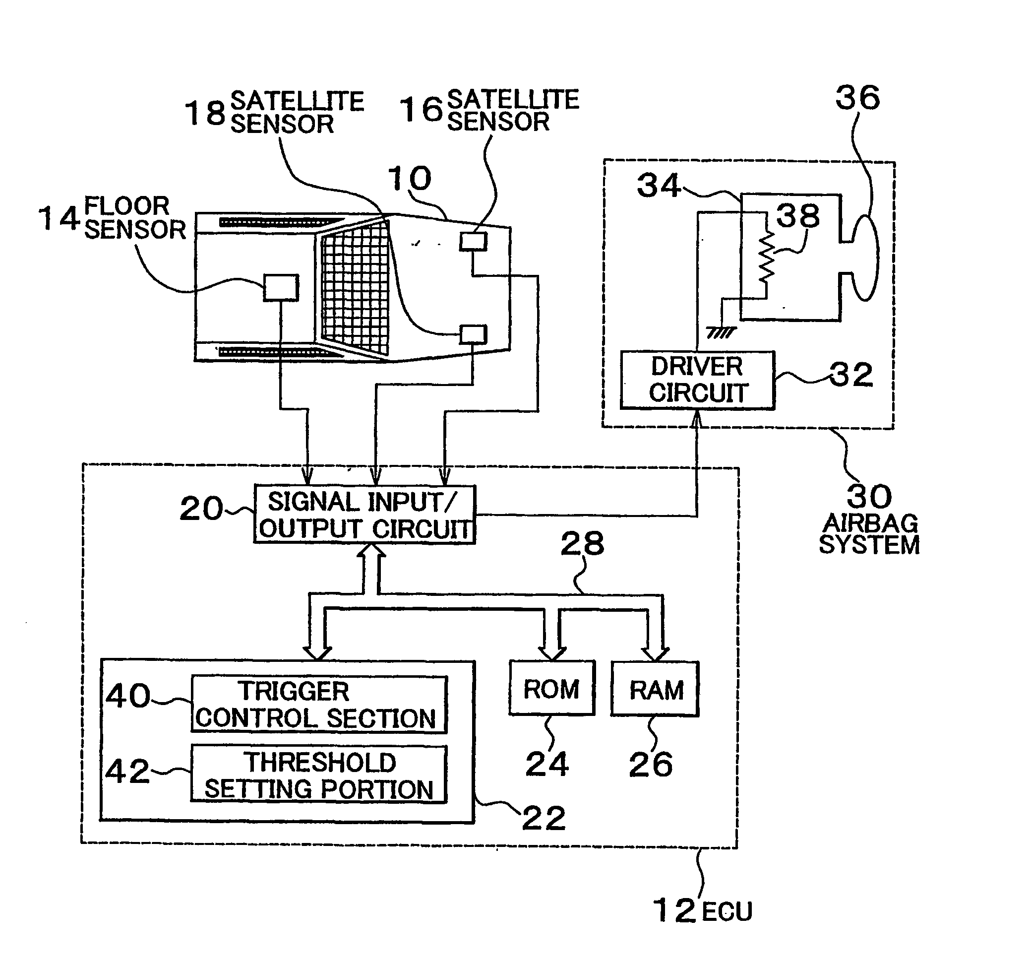
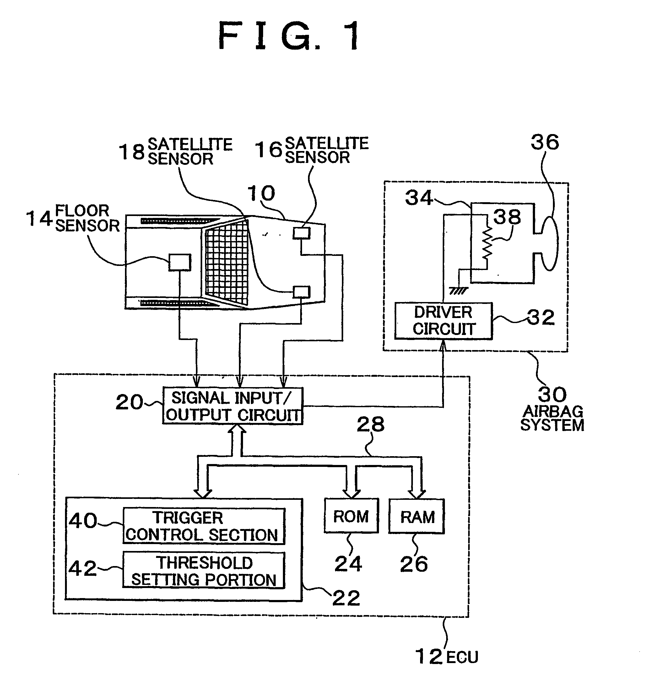
[0025] FIG. 1 schematically shows an airbag trigger control system according to a preferred embodiment of the invention. The airbag trigger control system of this embodiment includes an electronic control unit (hereinafter referred to as an "ECU") 12, which is installed in a vehicle 10. The airbag trigger control system operates under control of the ECU 12.

[0026] The airbag trigger control system of this embodiment further includes a floor sensor 14 and satellite sensors 16, 18. The floor sensor 14 is disposed in the vicinity of a floor tunnel located in a longitudinally intermediate portion of the vehicle 10, while the satellite sensors 16, 18 are respectively disposed in a left-side member and a right-side member located in the front of the vehicle 10. The floor sensor 14 and the satellite sensors 16, 18 may be electronic deceleration sensors, which are adapted to output signals corresponding to a magnitude of an impact exerted to respective portions of the vehicle 10 to which the...


PUM


Abstract

An airbag trigger control system is provided with a first sensor which is disposed in a predetermined position in a vehicle body and outputs a signal corresponding to an impact exerted to the vehicle body, a trigger control system which triggers an airbag when a parameter determined on the basis of the signal output from the first sensor exceeds a predetermined threshold value, a second sensor which is disposed forward of the first sensor in the vehicle body and outputs a signal corresponding to an impact exerted to the vehicle body, and a threshold value changing device which changes the predetermined threshold value in accordance with the signal output by the second sensor. The second sensor outputs a predetermined signal at predetermined intervals, and the threshold value changing device changes the predetermined threshold value to a given value when the output signal of the second sensor is not detected in a predetermined number of successive control cycles.

Description

[0001] 1. Field of the Invention[0002] The invention relates in general to an airbag trigger control system, and more particularly to an airbag trigger control system suitable for appropriately triggering an airbag system for protecting occupants in a vehicle upon collision of the vehicle.[0003] 2.Description of Related Art[0004] A known example of the conventional airbag trigger control system is disclosed in J-PA-11-286257. The disclosed airbag trigger control system includes a floor sensor disposed in a floor tunnel of a vehicle body. The floor sensor is operable to output a signal corresponding to an impact exerted to the floor tunnel. The airbag trigger control system is arranged to obtain control parameters on the basis of the output signals generated from the floor sensor and to control a trigger of the airbag system such that the airbag system is triggered when the obtained control parameters exceed a predetermined threshold value. In addition, the airbag trigger control sys...

Claims


Application Information

Patent Timeline
Patent Type & Authority Applications(United States)
IPC IPC(8): B60R21/01B60R21/0132B60R21/16
CPCB60R21/013B60R2021/01322B60R2021/01006B60R21/0132B60R21/0133B60R21/01
Inventor MIYATA, YUJIRONAGAO, TOMOKIIMAI, KATSUJIIYODA, MOTOMI
Owner TOYOTA JIDOSHA KK
Learn More