
Winding drum for sheet-like member

a technology of winding drum and sheet-like member, which is applied in the direction of instruments, printing, other domestic objects, etc., can solve the problems of increasing the manufacture cost affecting the quality of the winding drum, and generating unwanted contact marks on the sheet-like member, so as to prevent the generation of unwanted contact marks, improve the structure of the winding drum, and change the range of air intake holes reliably

Inactive Publication Date: 2010-08-17
THE YOKOHAMA RUBBER CO LTD
View PDF14 Cites 9 Cited by
  • Summary
  • Abstract
  • Description
  • Claims
  • Application Information

AI Technical Summary

Benefits of technology

The present invention provides a winding drum for a sheet-like member that can change the range of air sucking intake holes easily and prevent unwanted contact marks on the sheet-like member. This is achieved by providing a hollow portion in the drum body that is communicated with each intake hole and a changeover member that can be releasably attached in the hollow portion. The changeover member has an outer peripheral surface that extends along the inner peripheral surface of the hollow portion and an air passage that communicates intake holes of a predetermined range with the sucking means. The hollow portion is in communication with the intake holes, and the changeover member is rotatably provided in the hollow portion. This allows for easy adjustment of the range of air sucking intake holes and prevents unwanted contact marks on the sheet-like member.

Problems solved by technology

This complicates the structure of the winding drum and increases the manufacture cost of the winding drum.
Further, when a thin, soft sheet-like member such as an inner liner member is wound around the latter winding drum, the urging force urging the valve body toward the exterior of the winding drum may result in an unwanted contact mark on the sheet-like member.

Method used


Image

  • Winding drum for sheet-like member
  • Winding drum for sheet-like member
  • Winding drum for sheet-like member

Examples


Embodiment Construction

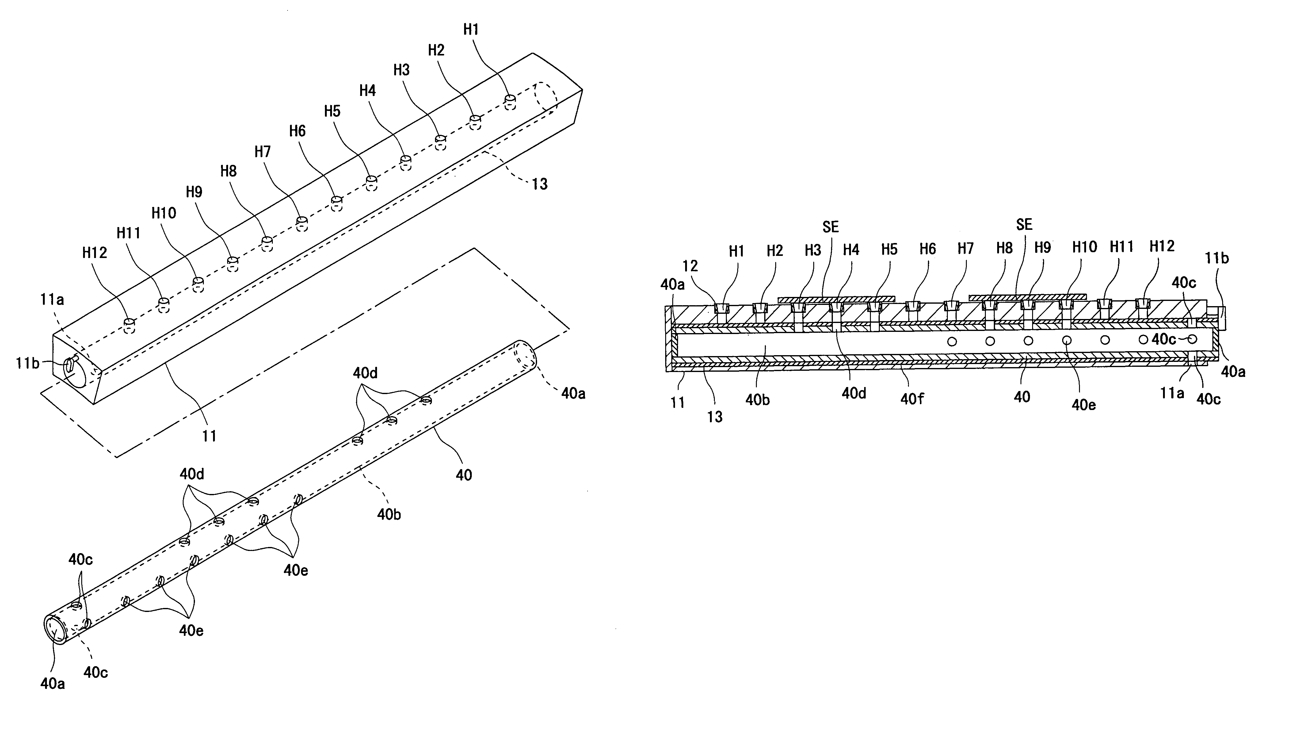
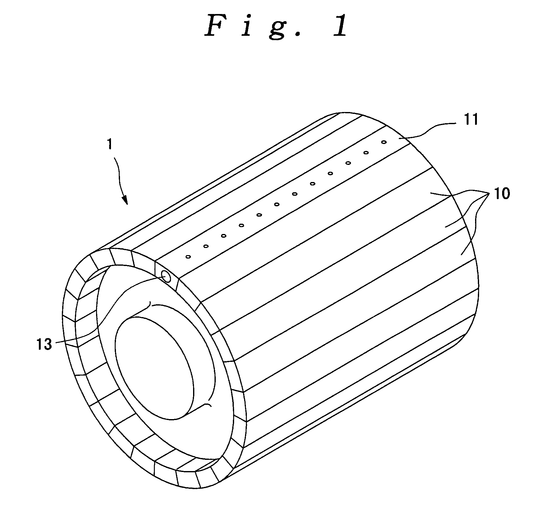
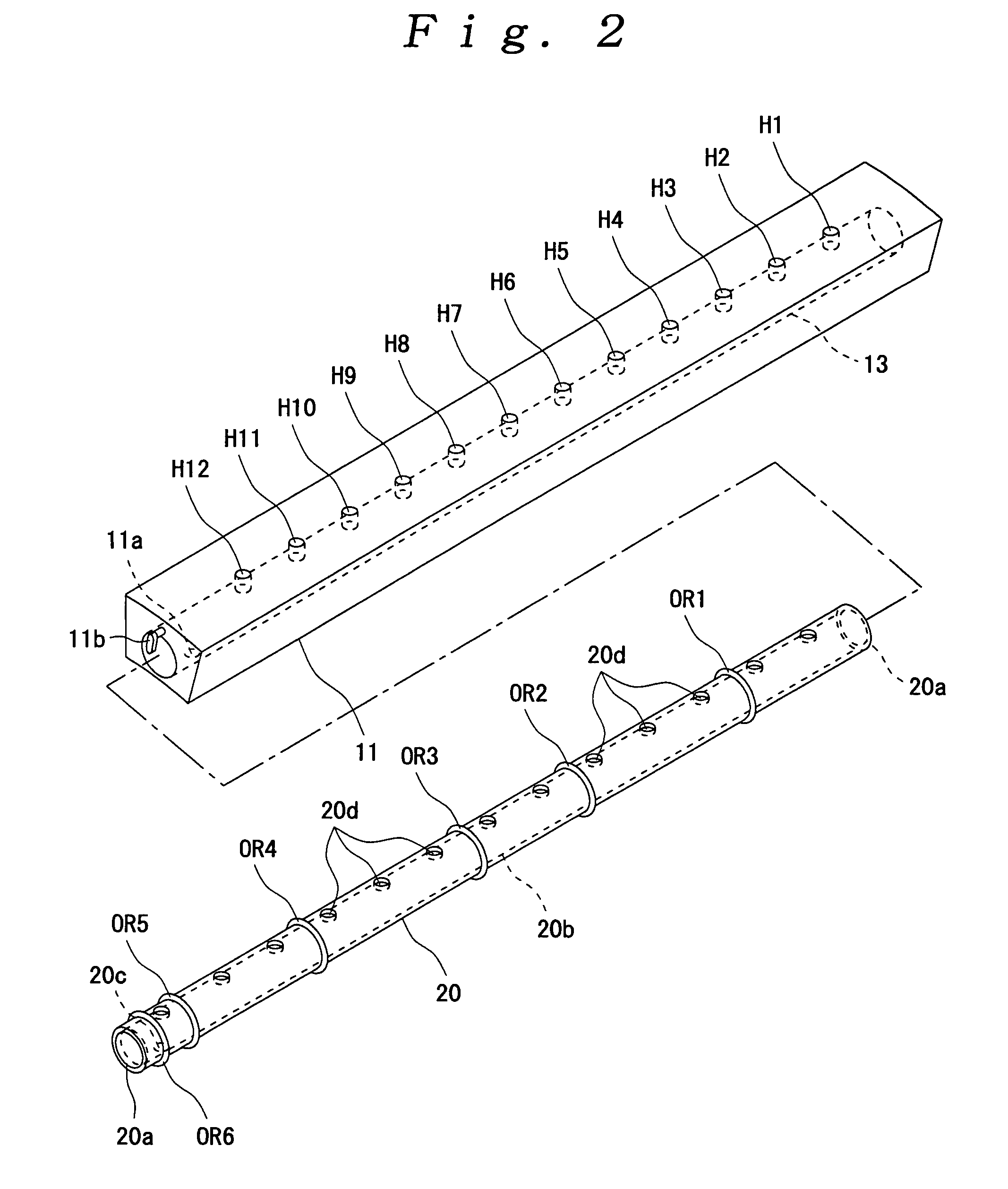
[0047]FIGS. 1 to 7 show a first embodiment of the present invention. FIG. 1 is a perspective view of a drum body showing a first embodiment of the present invention, FIG. 2 is a perspective view of a second drum member into which a changeover member has not been inserted yet, FIG. 3 is a side sectional view of the second drum member into which the changeover member has not been inserted yet, FIG. 4 is a side sectional view of the second drum member into which the changeover member has been inserted, FIG. 5 is a side sectional view showing an essential part of the second drum member into which the changeover member has been inserted, FIG. 6 is a side sectional view of the second drum member into which another changeover member has not been inserted yet, FIG. 7 is a diagram showing the relationship between the position of each intake hole and a winding position of a sheet-like member.

[0048]A winding drum for a sheet-like member comprises a plurality of first drum members 10 arranged a...


PUM

PropertyMeasurementUnit
cylindrical shapeaaaaaaaaaa
urging forceaaaaaaaaaa
structureaaaaaaaaaa

Abstract

The object of the present invention is to provide a winding drum for a sheet-like member which can change reliably the range of air sucking intake holes by a simple structure, and to provide a winding drum which can prevent the generation of an unwanted contact mark on the sheet-like member. This winding drum having a hollow portion which is in communication with the intake holes of the drum body, a changeover member which is releasably attached in the hollow portion and which is formed so as to extend along the inner peripheral surface of the hollow portion, and an air passage (second communicating holes, first communicating hole, and hole) which is provided on the changeover member and which communicates intake holes of a predetermined range in the axial direction of the drum body with the suction device when the changeover member is attached in the hollow portion. So the range of air sucking intake holes is switched by changing the changeover member to another changeover member with another air passage.

Description

TECHNICAL FIELD[0001]The present invention relates to, for example, a molding drum that is wound a sheet-like member such as an inner liner member, a sidewall member, or a carcass member which is a component of a tire of a vehicle so as to be molded into a cylindrical shape, and relates to a transfer drum that is wound the sheet-like member which is transferred to the molding drum.BACKGROUND ART[0002]A commonly known process of manufacturing a tire of a vehicle winds plural types of sheet-like members around an outer peripheral surface of a molding drum to mold a cylindrical member constituting a part of an uncured tire. Also, in other case, when the sheet-like member is wound around the molding drum, the sheet-like member may be wound once around an outer peripheral surface of a transfer drum that is different from the molding drum and the sheet-like member of the transfer drum is wound around the molding drum. A plurality of intake holes for sucking the sheet-like member by suckin...

Claims


Application Information

Patent Timeline
Patent Type & Authority Patents(United States)
IPC IPC(8): B65H19/28
CPCB29D30/242B65H19/2276B65H75/28B29D2030/241B29D2030/2692B29D2030/4468B29D2030/4493B65H2301/41426B65H2801/93
Inventor TANAKA, TOSHIOKIKUCHI, YOUICHIHASEGAWA, HARUHISA
Owner THE YOKOHAMA RUBBER CO LTD
Learn More