
Channel system for light strings

a light string and track technology, applied in the direction of curtain suspension devices, lighting and heating apparatus, lighting support devices, etc., can solve the problems of inconvenient light string installation methods, inconvenient use of light string mounting devices, and early deterioration of wooden mounting surfaces, so as to reduce the time for mounting lights and avoid the use of ladders and step stools

Inactive Publication Date: 2003-10-02
KMOR INNOVATIONS
View PDF0 Cites 15 Cited by
  • Summary
  • Abstract
  • Description
  • Claims
  • Application Information

AI Technical Summary

Benefits of technology

[0007] It is another object of the present invention to provide a channel system for ornamental light strings that is inconspicuously mountable onto the exterior / interior of a building and that allows for adjustable placement and removal of the ornamental light strings.
[0023] A still further object of the present invention is to provide an end cap to keep the light string from falling out of the end and to provide a hook to anchor the light string into final position.

Problems solved by technology

This method however, due to repetitive installation and removal of the staples, results in considerable marring of the wooden mounting surfaces and also can be dangerous because of potential damage to light string wires.
Staples and other sharp objects are not a recommended method of installation but lacking other convenient methods of light string installation are used by many.
Longs strings of lights, as are typically used, are difficult to install and consequently a householder is often inclined to leave the lights in place once they are secured.
Although this avoids yearly installation and removal, the strings of lights are exposed to weather for the full year resulting in their early deterioration and, furthermore, they add nothing to, and in fact detract from, the appearance of a house between holiday seasons.

Method used


Image

  • Channel system for light strings
  • Channel system for light strings
  • Channel system for light strings

Examples


Embodiment Construction

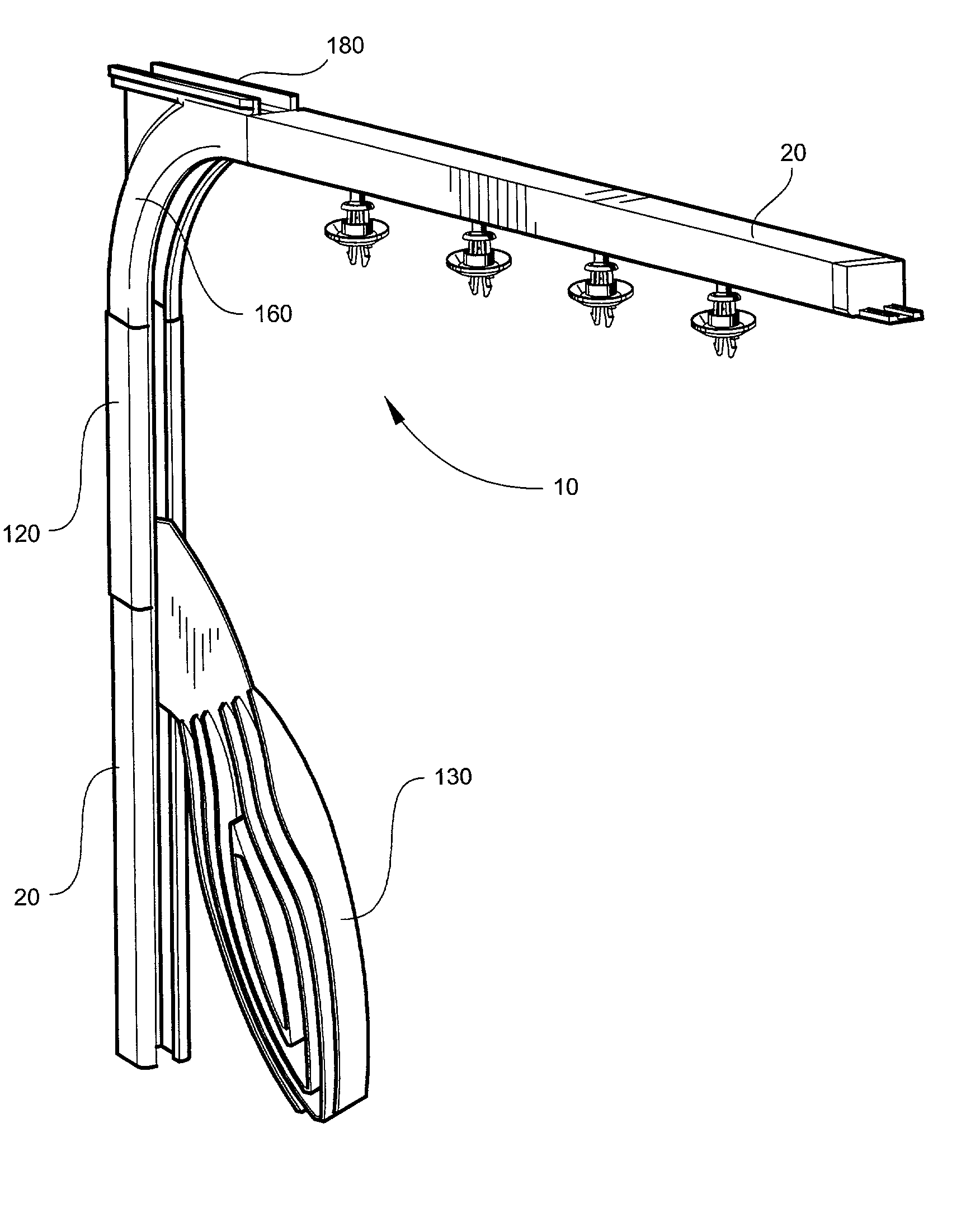
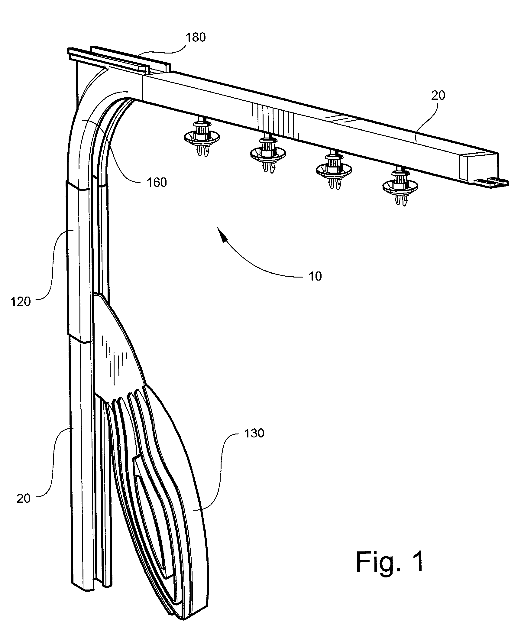
[0039] Referring now to the figures, the present invention is a kit or a channel system 10 useful for the removable mounting (installation and removal) of ornamental light strings onto buildings such as houses, offices, businesses, stores, and the like.

[0040] The system 10 according to the present invention has at least one, preferably a series of display channel pieces 20, or tracks, that are quasi-permanently attached to a surface of a building, such as a house, store, office, or the like. The channel pieces 20 are coupled together with coupling tabs 50. The preferred embodiment includes a comer piece that is provided to allow for three dimensions of mounting of the ornamental light strings. In an alternate embodiment, the channel pieces 20 are mitered at individual ends to closely fit the outline of the building while still allowing moveable mounting of the light strings.

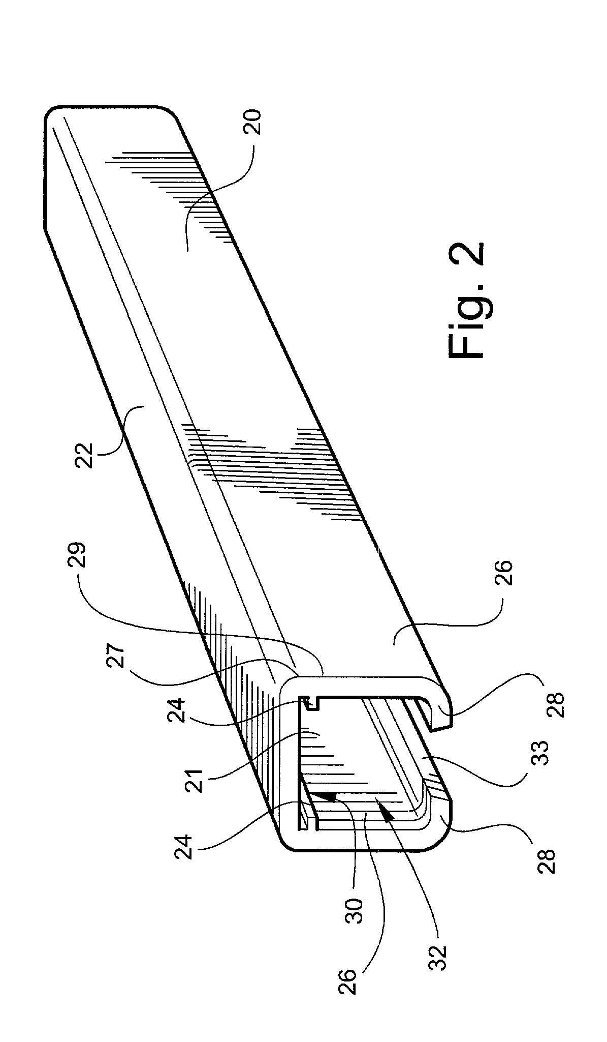
[0041] With reference to FIG. 2, the channel pieces 20 according to the present invention are long pieces, pre...


PUM


Abstract

The present invention is a kit or a channel system useful for the removable mounting (installation and removal) of ornamental light strings onto buildings such as houses, offices, stores, and the like. The system according to the present invention has at least one, preferably a series of, display channel pieces, or tracks, that are attached to a surface of a building, such as a house, store, office, or the like. The channel pieces are coupled together with coupling tabs. Slide mounts moveably fit within, and work with, channels within the channel pieces and are used to moveably secure ornamental light strings to the system when in use. Beveled edges located on distal ends of projections on the channel pieces allow for variable positioning of light strings using the channels system of the present invention. A slide mount guide is used to urge the mounted light string from a storage channel piece to the display channel pieces.

Description

FIELD OF THE INVENTION[0001] The present invention relates to the field of ornamental light string mounting devices. More specifically, the present invention relates to a channel track system for the moveable and removable mounting of ornamental light strings to the exterior and / or interior of buildings and the like.BACKGROUND[0002] It has become common practice to decorate homes, businesses, or other buildings during holiday seasons, such as Christmas, Halloween, Easter, and the like, by attaching strings of lights to achieve a decorative effect. The strings of lights are typically secured beneath overhanging eaves and around gables, and are also positioned to outline architectural features, whether interior or exterior, of the homes and businesses, such as windows, doorways, bars, and the like.[0003] The strings of lights are usually secured in place by simple connectors such as staples, hooks, nails and the like. This method however, due to repetitive installation and removal of ...

Claims


Application Information

Patent Timeline
Patent Type & Authority Applications(United States)
IPC IPC(8): F21S4/00F21V21/02
CPCF21S4/003F21V21/02Y10S362/806F21W2121/00F21W2131/107F21V21/34F21S4/20
Inventor MORELAND, KARREN
Owner KMOR INNOVATIONS
Learn More