
Intelligent vehicle air conditioning control system

Inactive Publication Date: 2003-09-11
INT TRUCK INTPROP LLC
View PDF4 Cites 16 Cited by
  • Summary
  • Abstract
  • Description
  • Claims
  • Application Information

AI Technical Summary

Benefits of technology

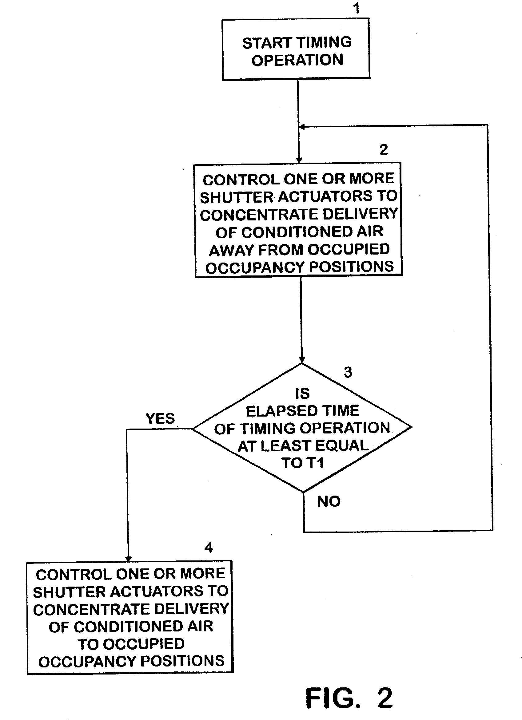
[0003] As a result, an object of the present invention is to provide an air conditioning control system which automatically causes the air conditioning system of a vehicle to maximize the flow rate of conditioned air to occupied areas of the occupant cabin 20 only when the conditioned air is most likely to be at a desirable temperature.
[0007] It can thus be seen that the present invention accomplishes the object of automatically maximizing the flow rate of conditioned air to the occupied areas of the occupant cabin only when the conditioned air is most likely to be at a desirable temperature.

Problems solved by technology

One problem with this system is that during a period following initiation of operation of the air conditioning system the conditioned air delivered to the occupied positions of the occupant cabin at an increased rate is often of an objectionable temperature.
In other words, in the summer when the occupant cabin is too warm, and operation of the air conditioning system is initiated, the conditioned air delivered to the occupants at an increased rate is often temporarily objectionably warm.
A similar situation often occurs in the winter when the conditioned air delivered by the air conditioning system is objectionably cold.
To control the air conditioning system to maximize the flow rate of conditioned air to the occupied areas of the occupant cabin during this time period when the conditioned air is of an undesirable temperature could thus increase the discomfort of the occupants.

Method used


Image

  • Intelligent vehicle air conditioning control system
  • Intelligent vehicle air conditioning control system
  • Intelligent vehicle air conditioning control system

Examples


Embodiment Construction

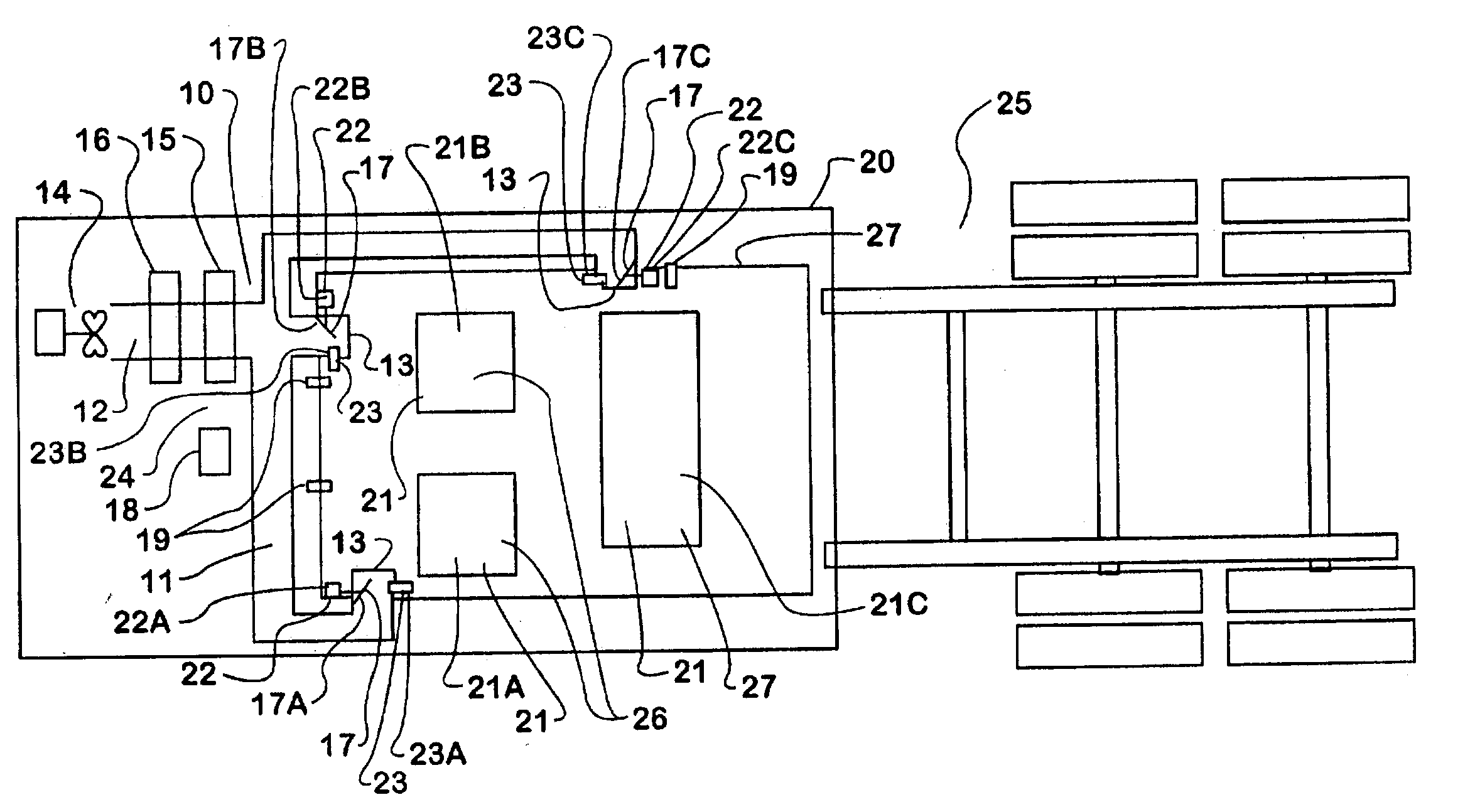
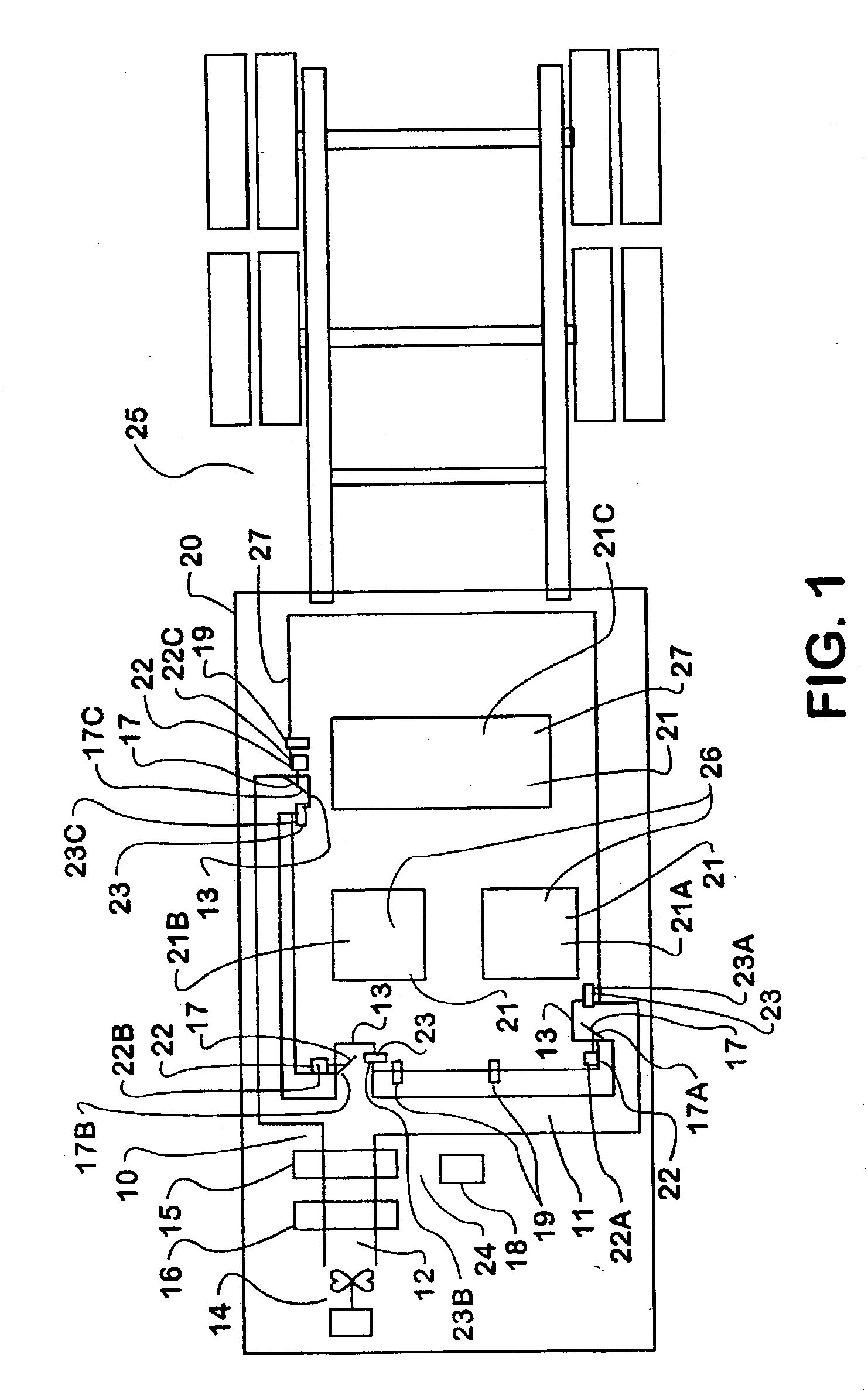
[0012] The present invention is an air conditioning control system 24 for a vehicle 25, a method of operating the air conditioning control system 24, and a computer executable program for causing operation of the air conditioning control system 24 in accordance with the method of operation of the invention. There is shown in FIG. 1 an air conditioning system 10, an air conditioning control system 24, and a vehicle 25 in accordance with the present invention. The air conditioning system 10 has a network of ducts 11 with an inlet 12 and a plurality of outlets 13 at various positions of the periphery 28 of the occupant cabin 20. The air conditioning system 10 has a blower 14 positioned such that when the blower 14 is in operation it causes air flow through the network of ducts 11 in the direction from the inlet 12 toward the plurality of outlets 13. The air conditioning system 10 has one or both of a heating element 15 and a cooling element 16 disposed within the network of ducts 11. T...


PUM


Abstract

An air conditioning control system for controlling the air conditioning system of a vehicle. The air conditioning control system is capable of determining the occupancy status of various locations in the vehicle interior. The air conditioning control system alters the flow rate of conditioned air to various portions of the vehicle interior based at least partially upon the occupancy of those areas of the vehicle interior. The air conditioning control system delivers increased amounts of conditioned air to the occupied portions of the vehicle interior when the conditioned air is of a comfortable temperature. The air conditioning control system delivers decreased amounts of conditioned air to the occupied portions of the vehicle interior when the conditioned air is most likely to be of an uncomfortable temperature.

Description

[0001] This invention relates to an intelligent air conditioning control system for a vehicle. The present invention is an air conditioning control system for a vehicle, a method of operating the air conditioning system, and a computer program embodied in a computer readable medium for causing the air conditioning control system to operate according to the method of the present invention, The air conditioning control system of the present invention causes the air conditioning system of a vehicle to deliver different flow rates of conditioned air to. various portions of the occupant cabin of the vehicle in order to improve occupant comfort and the efficiency of the air conditioning system. The distribution of flow rates of conditioned air within the occupant cabin is dependent upon the state of occupancy of various positions within the occupant cabin, and the temperature of the conditioned air or the elapsed time of operation of the air conditioning system.RELATED ART[0002] Conventio...

Claims


Application Information

Patent Timeline
IPC IPC(8): B60H1/00F24F11/00
CPCB60H1/00742B60H1/00835F24F13/08F24F11/0034F24F11/0078B60H1/00871F24F11/30F24F11/79F24F2120/10
Inventor PRICE, RALPH D.LAUKHUF, RODNEY A.
Owner INT TRUCK INTPROP LLC
Learn More