Latching micro-magnetic switch array

a micro-magnetic switch and array technology, applied in the field of electromechanical switches, can solve the problems of not retaining a constant output, the spring required by conventional micro-magnetic relays may degrade or break over time, and the relay is less desirable for use in space, portable electronics, and other applications that demand low power consumption

Inactive Publication Date: 2003-09-11
MAGFUSION
View PDF37 Cites 5 Cited by
  • Summary
  • Abstract
  • Description
  • Claims
  • Application Information

AI Technical Summary

Problems solved by technology

Such relays typically exhibit a number of marked disadvantages, however, in that they generally exhibit only a single stable output (i.e., the quiescent state) and they are not latching (i.e., they do not retain a constant output as power is removed from the relay).
Moreover, the spring required by conventional micro-magnetic relays may degrade or break over time.
Moreover, the power required to generate the opposing field would be significant, thus making the relay less desirable for use in space, portable electronics, and other applications that demand low power consumption.
Cross-point switch arrays are typically expensive, and must be manufactured to meet high performance standards.
In some conventional switch arrays, because the coils are not rectified, (i.e., do not limit the flow of current to one direction), the addressing of individual switches is difficult.

Method used


Image

  • Latching micro-magnetic switch array
  • Latching micro-magnetic switch array
  • Latching micro-magnetic switch array

Examples


Embodiment Construction

for Actuating a Micro-Magnetic Latching Switch in an Array of Switches

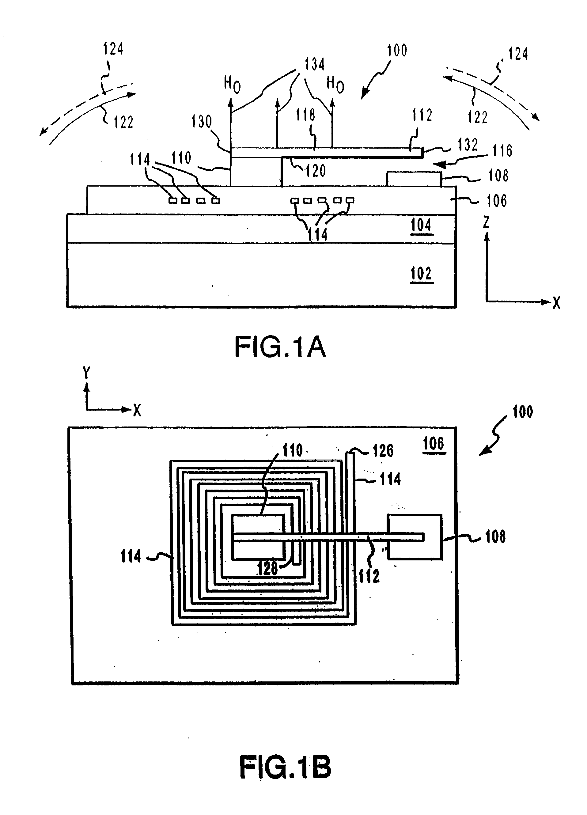
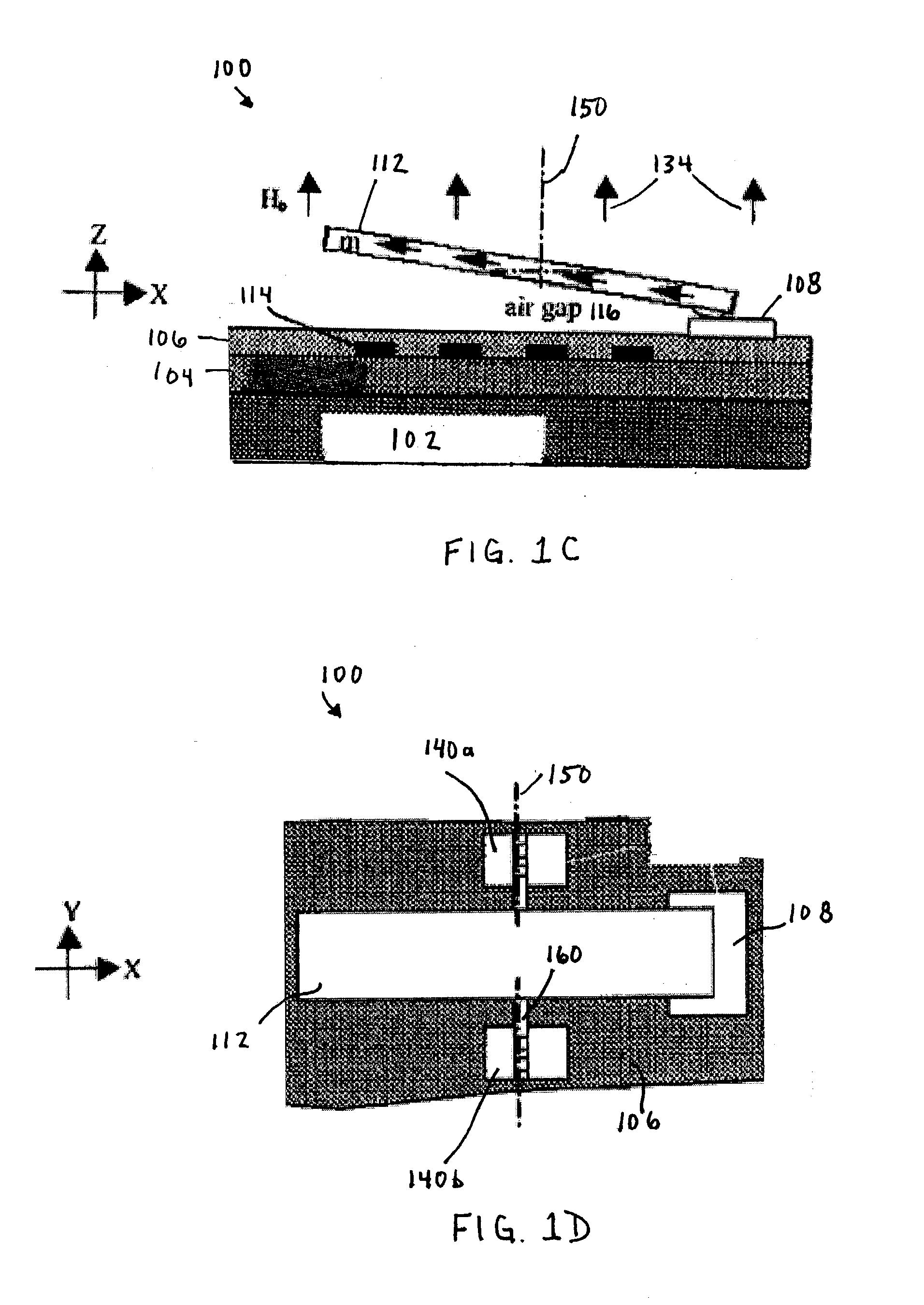
[0103] FIG. 10 shows a flowchart 1000 providing steps for actuating a micro-magnetic latching switch in an array of switches, according to an example embodiment of the present invention. For example, flowchart 1000 applies to the actuation of switches in two and three dimensional arrays of switches, such switches in system 400 shown in FIG. 4, system 600 shown in FIG. 6, and system 900 shown in FIG. 9. In an embodiment, switches are configured similarly to switch or relay 100 shown in FIGS. 1A-1D, except where coil 114 may be physically separate from relay 100, such as in row of coils 404, or in a separate array of coils 602. Other structural and operational embodiments will be apparent to persons skilled in the relevant art(s) based on the following discussion. These steps are described in detail below.

[0104] Flowchart 1000 begins with step 1002. In step 1002, a first magnetic field is produced which induces a ma...


PUM


Abstract

Systems and methods for actuating micro-magnetic latching switches in an array of micro-magnetic latching switches are described. The array of switches is defined by Y rows aligned with a first axis and X columns aligned with a second axis. Each switch in the array of switches is capable of being actuated by a coil. In an aspect, a row of coils is moved along the second axis to be positioned adjacent to a selected one of the Y rows of switches. A sufficient driving current is proved to a selected coil in the row of coils to actuate a selected switch in the selected one of the Y rows of switches. In another aspect, a plurality of first axis drive signals and a plurality of second axis drive signals are generated. These signals drive an array of coils, wherein each coil in the array of coils is positioned adjacent to a corresponding switch in the array of switches. Each first axis drive signal is coupled to coils in a corresponding column of coils in the array of coils. Each second axis drive signal is coupled to coils in a corresponding row of coils in the array of coils. In another aspect, a three-dimensional array of switches is actuated by drive signals that drive a three-dimensional array of coils.

Description

[0001] This application claims priority to U.S. provisional Application No. 60 / 341,864, filed Dec. 21, 2001, which is incorporated herein by reference.[0002] 1. Field of the Invention[0003] The present invention relates to electronic switches. More specifically, the present invention relates to an array of latching micro-magnetic switches.[0004] 2. Background Art[0005] Switches are typically electrically controlled two-state devices that open and close contacts to effect operation of devices in an electrical or optical circuit. Relays, for example, typically function as switches that activate or deactivate portions of electrical, optical or other devices. Relays are commonly used in many applications including telecommunications, radio frequency (RF) communications, portable electronics, consumer and industrial electronics, aerospace, and other systems. More recently, optical switches (also referred to as "optical relays" or simply "relays" herein) have been used to switch optical s...

Claims


Application Information

Patent Timeline
Patent Type & Authority Applications(United States)
IPC IPC(8): H01H50/00H01H51/22H01H67/22
CPCH01H50/005H01H2050/007H01H67/22
Inventor SHEN, JUNWEI, CHENG PING
Owner MAGFUSION
Why Eureka
Try Eureka