
Method and apparatus for producing decabromodiphenyl alkanes

a technology of diphenyl alkane and diphenyl alkane, which is applied in the field of methods and apparatus for producing decabromodiphenyl alkane, can solve the problems of manufacturer being unable to stop, the dip tube used for adding diphenyl alkane to the vessel is prone to plugging

Inactive Publication Date: 2003-07-31
GREAT LAKES CHEM CORP
View PDF0 Cites 17 Cited by
  • Summary
  • Abstract
  • Description
  • Claims
  • Application Information

AI Technical Summary

Benefits of technology

[0013] In accordance with the present invention, the crude decabromodiphenyl alkane, such as decabromodiphenylethane, obtained by the aforementioned process is isolated and purified. Any one of numerous known isolation and purification methods may be utilized. For example, the solid may be isolated through direct removal from the slurry by filtration or centrifugation. The solid decabromodiphenyl alkane could as be removed by combining the reaction mass with water and striping the bromine through the use of heat and / or a vacuum. In one method of the invention, the crude decabromodiphenyl alkane is first made into a water slurry, and is transferred to a another reactor. The slurry is washed with an alkaline solution and the solid decabromodiphenyl alkane is separated and washed with water. The solid decabromodiphenyl alkane is then in the form of a filter cake. The filter cake may be treated in any one of a number of known ways. For example, the cake may first be dried and then fractured and / or heat treated in a number of ways. The wet decabromodiphenyl alkane product may also be treated without first drying, as disclosed in U.S. Pat. No. 4,659,021 to Bark, et al. In one embodiment of the present invention, the filter cake is dried and then ground twice in an air mill using air which is heated to an inlet temperature of approximately 260.degree. C. The ground decabromodiphenyl alkane is then heat-treated at approximately 240.degree. C. for three to four hours in order to release any free bromine which may be present in the product. The release of free bromine improves the purity and the color of the end product. Other known isolation and purification methods may also be utilized, such as those disclosed in U.S. Pat. No. 4,327,227 to Ayres, et al. and U.S. Pat. No. 5,030,778 to Ransford.
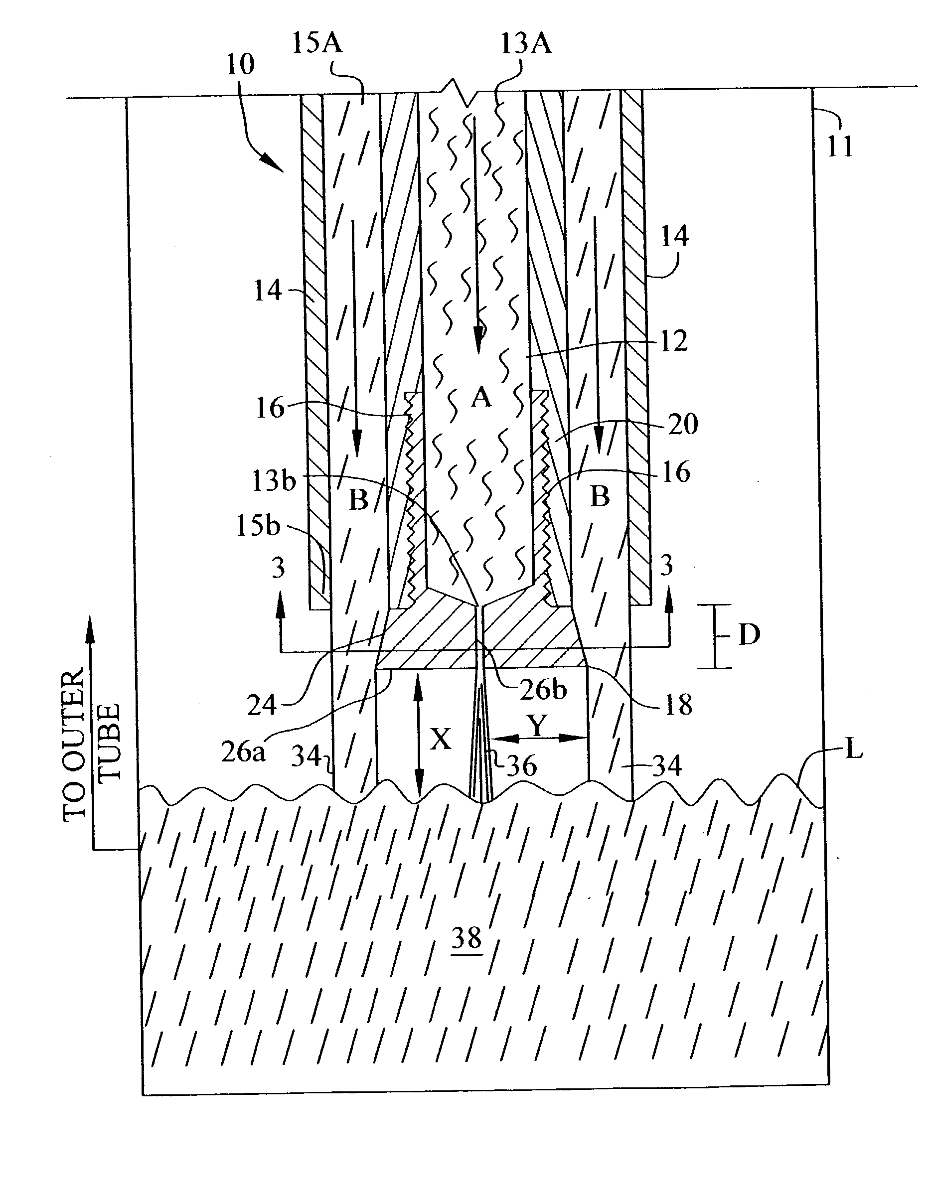
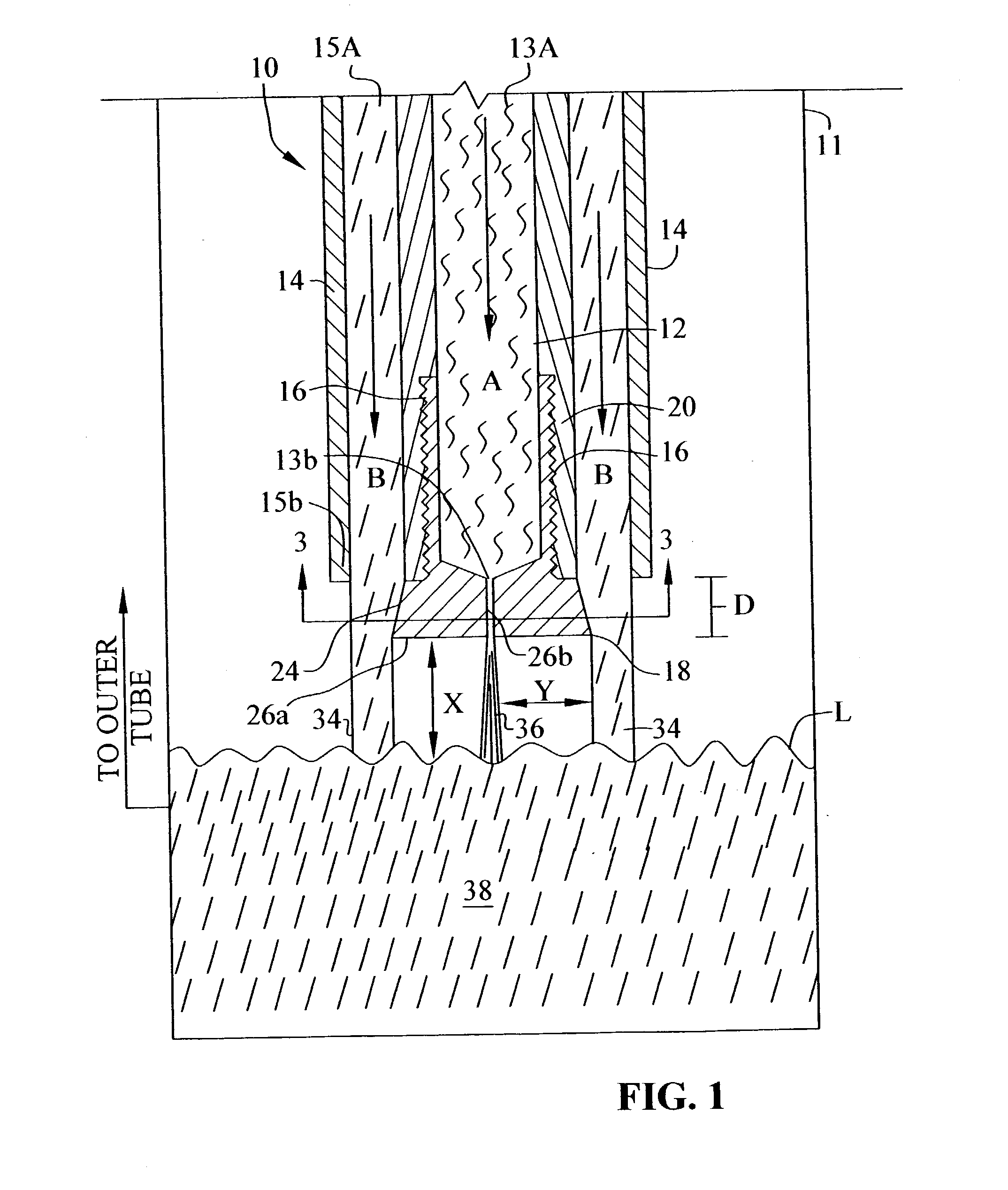
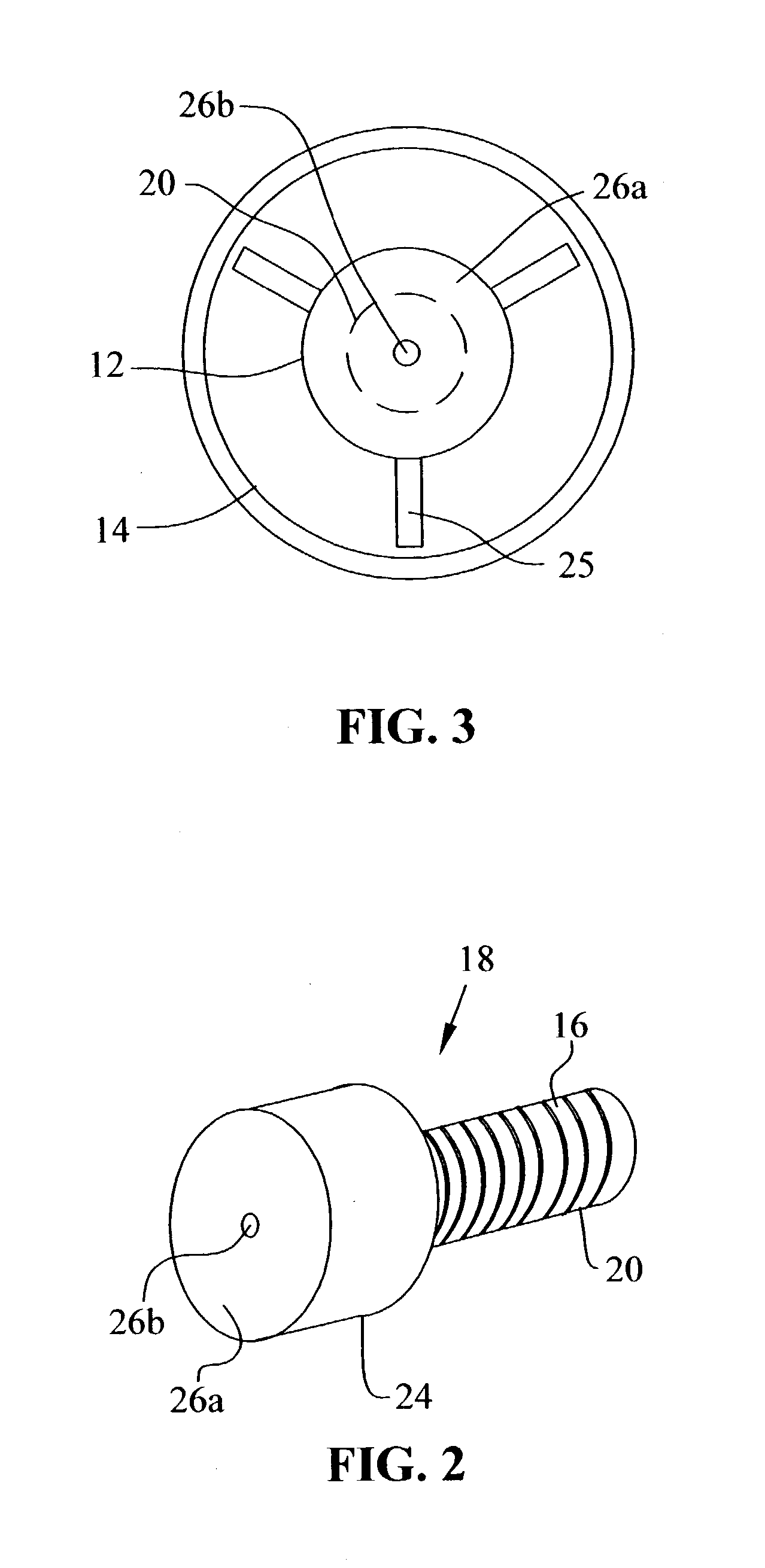
[0014] An apparatus for preparing decabromodiphenyl alkanes according to the present invention includes a dip tube apparatus disposed above the surface level of the charged liquid bromine in the reaction vessel and includes an inner tube and an outer tube. The inner tube has a first end and a second end. The first end is adapted to receive a flow of diphenyl alkane. The second end of the inner tube is adapted to receive a plug. The plug includes a hollow portion and an opening. When the inner tube and the plug are engaged, the plug and the inner tube are in fluid communication with one another. The diphenyl alkane flows through the inner tube, through an opening in the plug, and into the reaction vessel at a location which is above the surface level of the charged liquid bromine and the bromination catalyst. Plugs having a variety of opening sizes and configurations may be chosen in order to achieve the desired flow rate diphenyl alkane. Alternatively, the plug can be eliminated and the opening through which the diphenyl alkane flows can be formed in one end of the inner tube.

Problems solved by technology

One disadvantage to adding the diphenyl alkane to the vessel at a location below the surface of the charged bromine and catalyst is that the dip tubes used for adding the diphenyl alkane to the vessel are prone to plugging.
This susceptibility to plugging prevents the manufacturer from being able to stop and start the diphenyl alkane addition, which is sometimes desirable for controlling the evolution HBr gas.
This vortex may pull solids from the reaction mass into the tube, thereby creating a blockage.

Method used


Image

  • Method and apparatus for producing decabromodiphenyl alkanes
  • Method and apparatus for producing decabromodiphenyl alkanes
  • Method and apparatus for producing decabromodiphenyl alkanes

Examples


Embodiment Construction

[0033] A 3000 gallon glass lined Pfaudler reactor was equipped with a vertical H-type baffle, condenser system, 41" Pfaudler Cryo-lock reverse curve agitator, temperature sensor, and the dip tube apparatus described above. 21,210 kg (132,278.41 moles) of liquid bromine and 63.5 kg (476.26 moles) of aluminum chloride were charged to the reaction vessel. The agitator was then turned on and ranged in speed from 47 to 88 rpm. The reactor was heated to 55.degree. C. 618 kg (3395.6 moles) of DPE was then charged through the dip tube, as described above, at a rate of 4-8.5 lbs. / min. The DPE addition ranged from 3.5 to 5 hours. Once the feed was completed, the reaction temperature was increase to 60.degree. C. and held at that temperature for thirty minutes.

[0034] A 4000 gallon glass lined Pfaudler reactor was equipped with a vertical H-type baffle, condenser system, 41" Pfaudler Cryo-lock reverse curve agitator, and temperature sensor. The vessel was charged with 1850 gallons of water. The...


PUM

PropertyMeasurementUnit
Timeaaaaaaaaaa
Pressureaaaaaaaaaa
Angleaaaaaaaaaa

Abstract

A method of producing decabromodiphenyl alkanes includes the steps of charging a reaction vessel with bromine and a bromination catalyst and introducing a diphenyl alkane into the vessel at a location above the level of the charge bromine and catalyst. A dip tube apparatus for introducing the diphenyl alkane includes an inner tube and an outer tube, each of which are disposed above the surface of the bromine reaction vessel. The inner tube is fitted with a plug having an opening. Diphenyl alkane flows through the inner tube, out the opening in the plug, and into the reactor. The outer tube is disposed around and along the inner tube. Reaction mass from the vessel is recirculated from the vessel, through the outer tube and back to the vessel so as to form a curtain of reaction mass around the stream of diphenyl alkane being simultaneously fed into the reaction vessel.

Description

[0001] This application claims the benefit of U.S. Provisional Patent Application Serial No. 60 / 345,063 filed Dec. 21, 2001, the complete disclosure of which is hereby expressly incorporated by reference.[0002] 1. Field of the Invention[0003] This invention relates to methods and an apparatus for producing decabromodiphenyl alkanes. More specifically, the field of the invention is that of producing decabromodiphenyl ethane.[0004] 2. Description of the Related Art[0005] Halogenated aromatic compounds are often employed as flame retardant agents. Flame retardants are substances applied to or incorporated into a combustible material to reduce or eliminate its tendency to ignite when exposed to a low-energy flame, e.g., a match or a cigarette. The incorporation of flame retardants into the manufacture of electronic equipment, upholstered furniture, construction materials, textiles and numerous other products is well known.[0006] Brominated aromatic compounds are often utilized as flame ...

Claims


Application Information

Patent Timeline
IPC IPC(8): B01J8/00B01J8/02B01J8/16B01J19/26C07C17/12
CPCB01J8/008B01J8/0278B01J8/16B01J19/26C07C17/12B01J2208/003C07C25/18
Inventor FALLOON, STEPHEN B.MULLIGAN, SAMUELMCELVEEN, DONAVON W.ATWELL, RAY W.
Owner GREAT LAKES CHEM CORP
Learn More