Surgical instrument for minimally invasive surgical interventions
- Summary
- Abstract
- Description
- Claims
- Application Information
AI Technical Summary
Benefits of technology
Problems solved by technology
Method used
Image
Examples
first embodiment
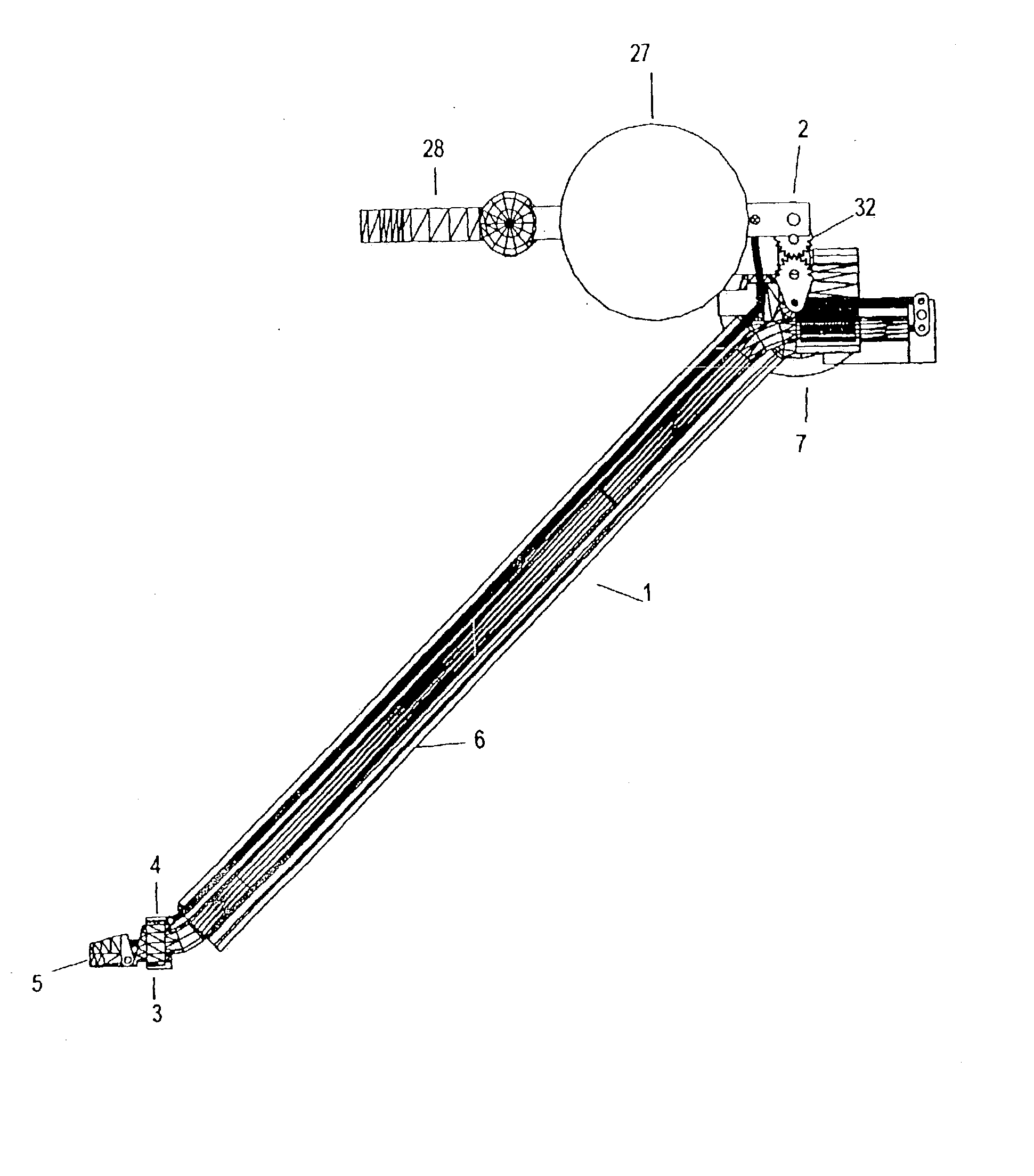
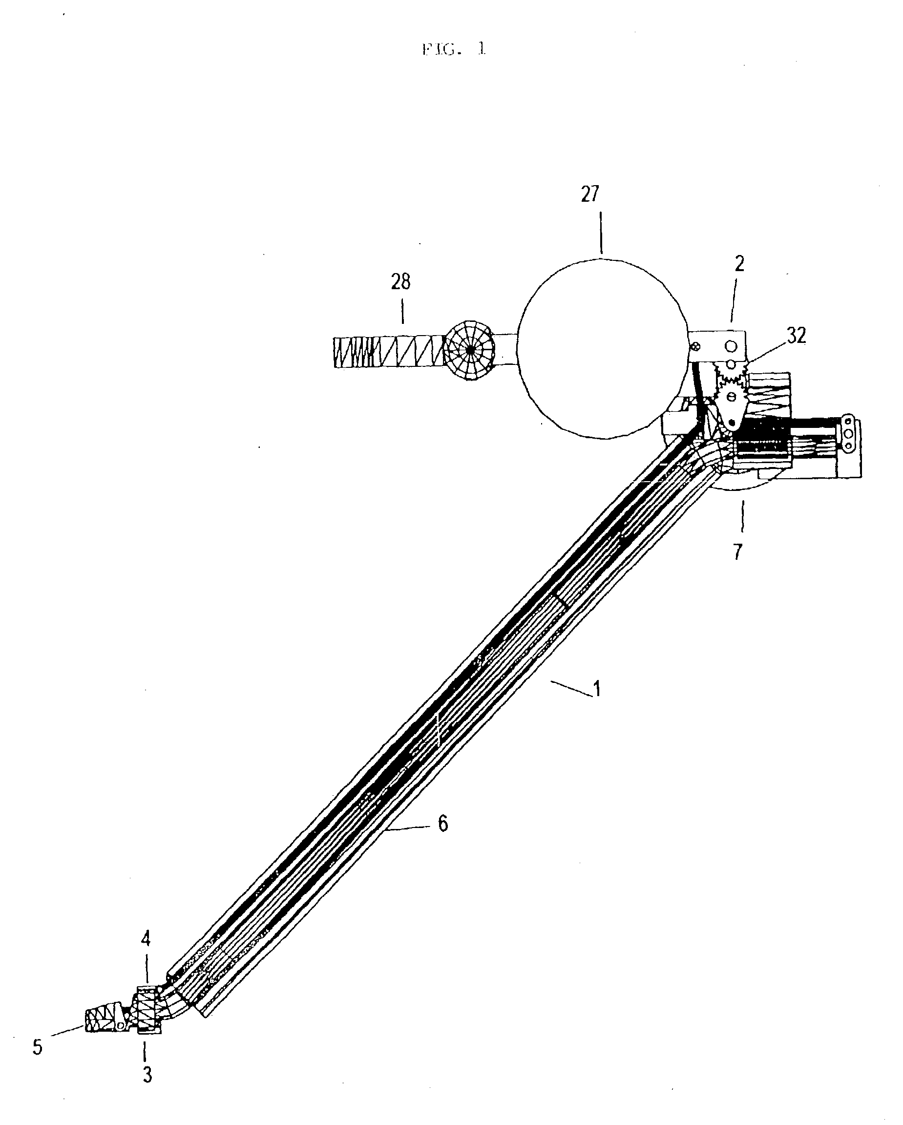
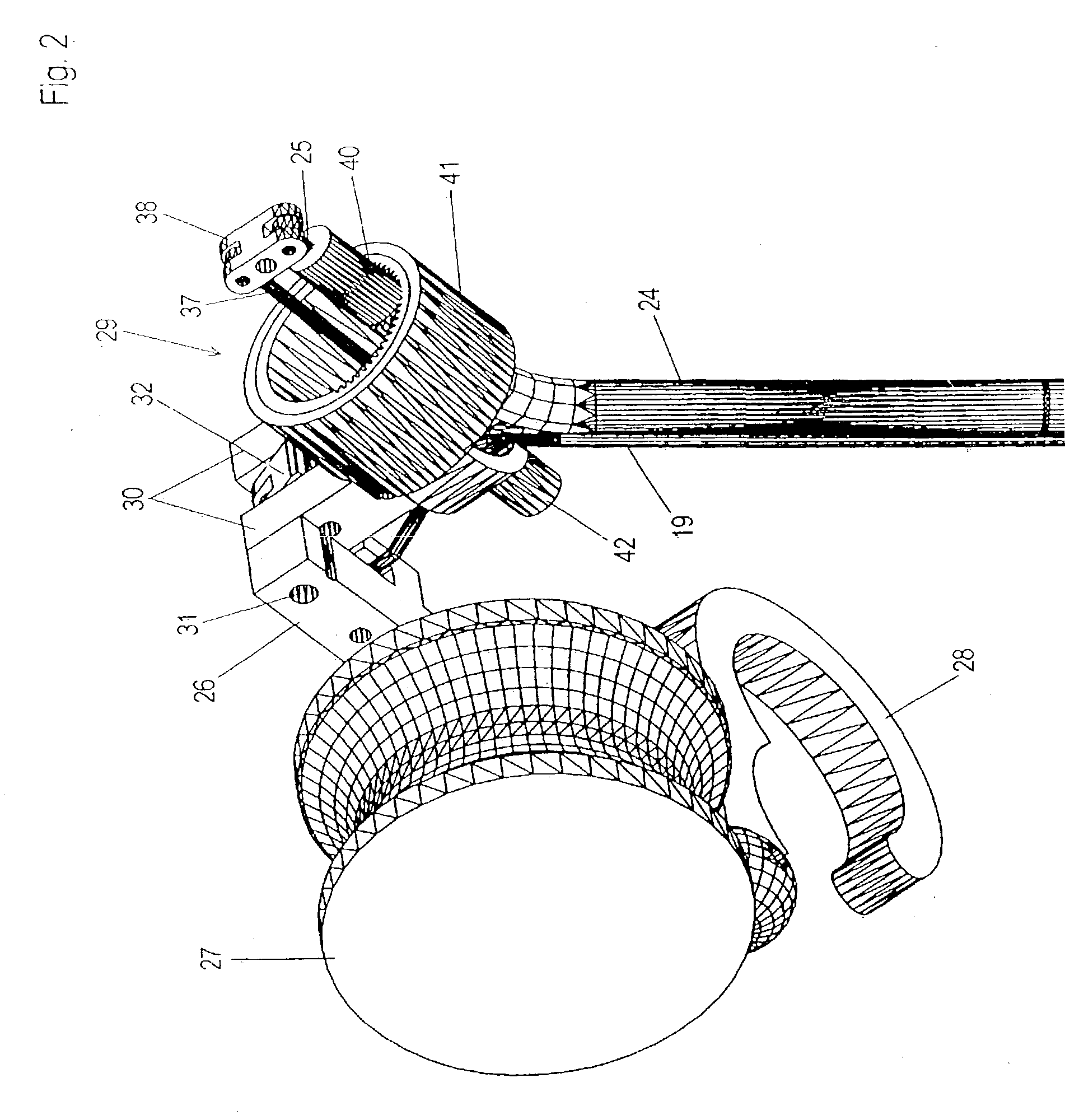
[0034] As shown in FIG. 1, a surgical instrument according to the present invention includes a hollow shank 1 preferably made of a deflection-resistant and torsion-resistant material or structure. An actuating device 2 is arranged at a first axial end portion of the hollow shank 1, hereinafter referred to as the proximal end portion. An instrument tip 3 having a case-like seat 4 for rotatably carrying a mouth part 5 is arranged at the second axial end of the hollow shank 1, hereinafter referred to as the distal end portion, the seat being pivotable toward the proximal end portion of the hollow shank 1. The surgical instrument further includes a force and / or torque transmission mechanism (gear mechanism) through which both the seat 4 and the mouth part 5 are mechanically coupled with the actuating device 2 for the independent actuation thereof.
[0035] The hollow shank 1 is formed by an oblong substantially deflection-resistant tubular piece 6 of a non-oxidizing metal which is cut squa...
second embodiment
[0057] the present invention will now be described with reference to FIGS. 6-11, wherein the same reference numerals are used for similar parts in the above-described embodiment.
[0058] In accordance with FIG. 6, a further embodiment of the surgical instrument likewise comprises an actuating device 2 or a grip end, a hollow shank 1 and an instrument tip 3 which is mechanically coupled with the grip end by a force / torque transmission mechanism.
[0059] The hollow shank 1 includes a substantially inflexible tubular piece 6 made of a non-oxidizing material which is cut square at its two ends. A bracket-shaped projection 50 is formed or fastened to the distal end of the hollow shank 1 (see FIG. 7). A through hole aligned tangentially with respect to the tubular piece 6 is arranged at an edge side of the projection 50. A mounting structure for attaching the actuating device is formed at the proximal end of the hollow shank 1.
[0060] According to FIGS. 7 and 8, the instrument tip 3 has a case...
PUM
 Abstract
Description
Claims
Application Information
 - R&D
- Intellectual Property
- Life Sciences
- Materials
- Tech Scout
- Unparalleled Data Quality
- Higher Quality Content
- 60% Fewer Hallucinations
Browse by: Latest US Patents, China's latest patents, Technical Efficacy Thesaurus, Application Domain, Technology Topic, Popular Technical Reports.
© 2025 PatSnap. All rights reserved.Legal|Privacy policy|Modern Slavery Act Transparency Statement|Sitemap|About US| Contact US: help@patsnap.com


