
Inclinometer with bragg grating

a technology of inclinometer and bragg grating, which is applied in the direction of speed measurement using gyroscopic effects, instruments, gyroscopes/turn-sensitive devices, etc., can solve the problems of high price of inclinometer, not very suitable for geotechnical or civil engineering applications

Inactive Publication Date: 2003-05-22
COMMISSARIAT A LENERGIE ATOMIQUE ET AUX ENERGIES ALTERNATIVES
View PDF1 Cites 20 Cited by
  • Summary
  • Abstract
  • Description
  • Claims
  • Application Information

AI Technical Summary

Benefits of technology

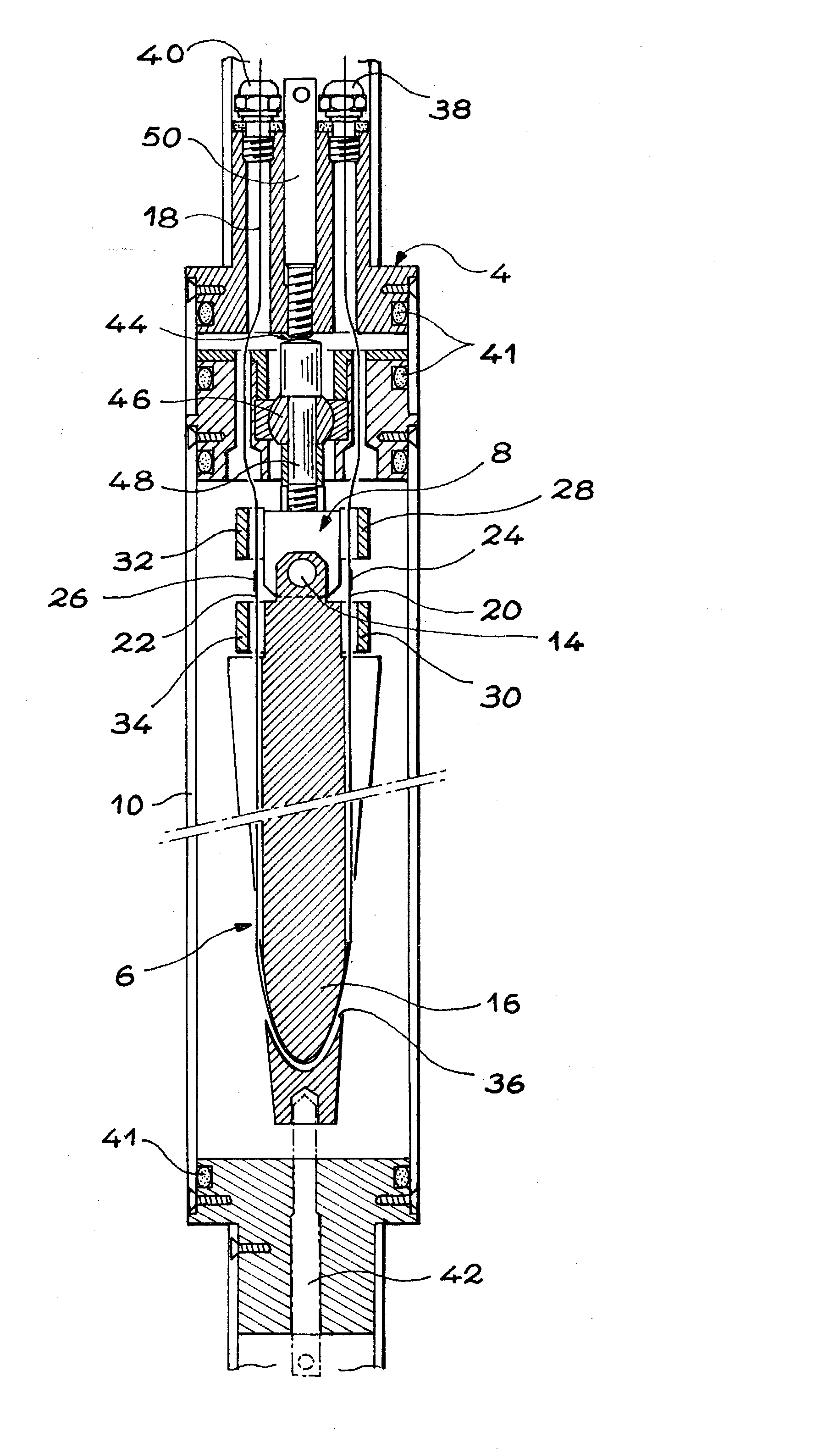
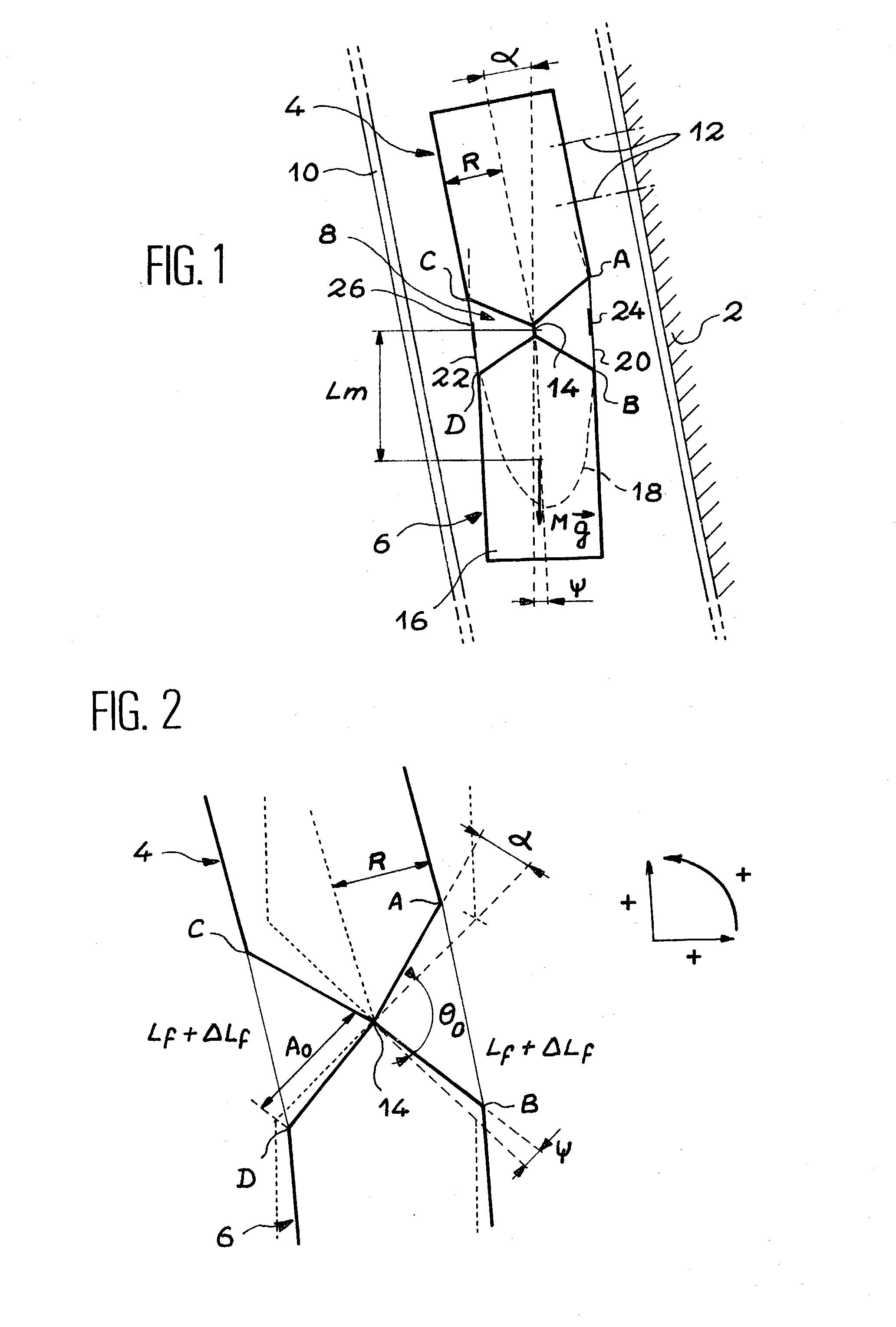
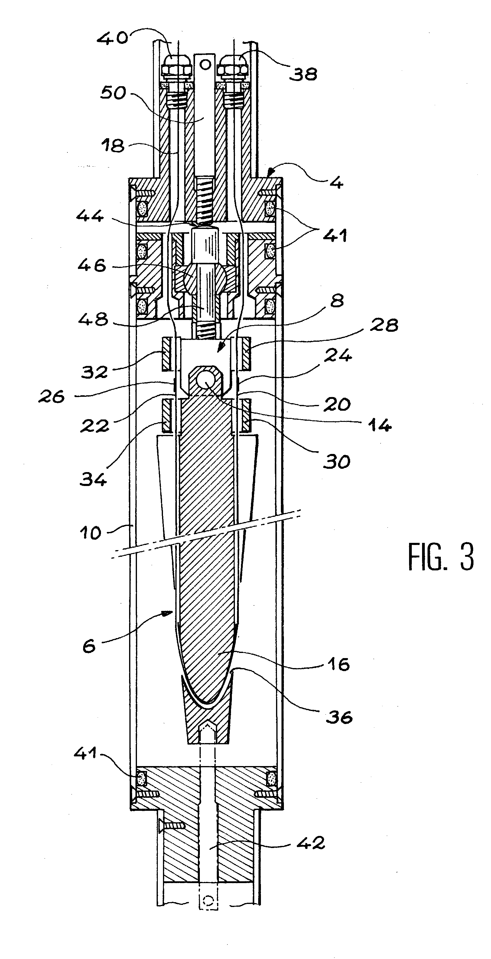
[0042] According to a preferred embodiment, the inclinometer according to the invention comprises at least two Bragg gratings, said two Bragg gratings being respectively formed in the two portions of optic fibre and thus undergoing respectively a tensile stress and a compressive stress during the variation of inclination of the structure, said Bragg gratings making it possible to carry out a differential measurement of the wave length, the inclinometer then being insensitive to variations in ambient temperature and pressure.
[0044] According to a specific embodiment of the inclinometer of the invention, the articulation of the lower and upper parts has at least two degrees of freedom of rotation, said inclinometer comprising at least three portions of optic fibre put under tension and placed around said articulation and at least two Bragg gratings, said two Bragg gratings being respectively formed in two of the three portions of optic fibre, the inclinometer then being provided for measuring an inclination variation definable by two angles of rotation. It is more advantageous to form a third Bragg grating in the third portion of optic fibre, in order to obtain a third measurement, used to compensate the effect of temperature.

Problems solved by technology

As a result, it is not very suitable for geotechnical or civil engineering applications.
Such inclinometers are expensive, especially when they are used in a network.

Method used


Image

  • Inclinometer with bragg grating
  • Inclinometer with bragg grating
  • Inclinometer with bragg grating

Examples


Embodiment Construction

[0034] The aim of the present invention is an inclinometer that is insensitive to electromagnetic perturbations and which, in order to achieve this, uses one or a plurality of optic fibres as well as at least one Bragg grating as transducer.

[0035] Moreover, in the invention, spectral type measurements make it possible to disregard light intensity fluctuations.

[0036] More precisely, the aim of the present invention is an inclinometer intended to measure an inclination variation of a structure, said inclinometer being characterised in that is comprises:

[0037] an upper part intended to be rendered rigidly integral with the structure so that the inclination of said upper part varies like that of the structure,

[0038] a lower part intended to be located below the upper is part,

[0039] an articulation of the lower and upper parts, the lower part forming a pendulum freely suspended from the upper part by this articulation,

[0040] at least two portions of optic fibre placed on either side of s...


PUM


Abstract

This inclinometer comprises an upper part (4), a lower part (6) forming a pendulum suspended from the upper part by an articulation (8), at least two portions of optic fibre (20, 22) placed on either side of said articulation, the ends of each portion being fastened to the two parts, each portion being previously put under tension between said parts, and at least one Bragg grating (24) in one of the portions. Any variation in the inclination of a structure to which is fastened the upper part induces a stress on the grating, which then modifies a light propagating in the portion where it is placed. The variation in inclination is determined from the modified light. The invention applies in particular to the surveillance of civil engineering structures.

Description

[0001] The present invention concerns an inclinometer, in other words a device intended to measure inclination variations.[0002] In particular, the invention can be used in mines, drillings, in the civil engineering field, for the surveillance of civil engineering structures (for example bridges and tunnels) and buildings (in particular, historical monuments), and anywhere where a precise control of the stability of a structure is required, particularly over the long term.STATE OF THE PRIOR ART[0003] Diverse methods of auscultation are customarily used to monitor the amplitude and the rate of distortion, whether horizontal or vertical, of structures, of the surface of the ground and of accessible sub-soil parts in various categories of construction.[0004] Customarily, in civil engineering, instruments called "extensometers" are used to monitor distortions. Various extensometers are commercially available.[0005] As regards rotation measurements, electric inclinometers, also called "t...

Claims


Application Information

Patent Timeline
IPC IPC(8): G01B11/16G01B11/26G01C9/12
CPCG01B11/165G01C9/12G01B11/26G01B11/18
Inventor FERDINAND, PIERREROUGEAULT, STEPHANE
Owner COMMISSARIAT A LENERGIE ATOMIQUE ET AUX ENERGIES ALTERNATIVES
Learn More