
Shoe incorporating improved shock absorption and stabilizing elements

a technology of stabilizing elements and shock absorption, which is applied in the field of footwear construction, can solve the problems of excessive pronation of the user's foot, reducing the ability of the tabs to resist compression of the heeled wedge and midsole, and injuring the wearer of the sho

Inactive Publication Date: 2003-04-03
SEQUENTIAL AVIA HLDG LLC
View PDF16 Cites 53 Cited by
  • Summary
  • Abstract
  • Description
  • Claims
  • Application Information

AI Technical Summary

Benefits of technology

[0015] It is another object of the present invention to provide improved shock absorption and stability for a shoe through the use of cooperating midsole and shock absorbing elements.
[0017] It is still yet another object of the present invention to provide improved, dynamic stability for a shoe through the use of unsymmetrical stabilizing pods.

Problems solved by technology

The tendency for excessive lowering of the medial margin of the foot or excessive pronation, and a tendency for an excessive raising of the medial margin of the foot, or supination, have the potential of causing injuries to the wearer of the shoe.
Since the tabs are secured to the extreme outer edges of the heel wedge and midsole, this will reduce the ability of the tabs to resist compression of the heeled wedge and midsole in the areas of the wedge and midsole inside the shoe surrounding the user's foot.
Irrespective of the number of fluid filled cylinders embedded Eli within the heel, excessive pronation of the user's foot will occur since the air cylinders cannot properly respond to the difference in forces imposed on the medial and lateral portions of the heel.

Method used


Image

  • Shoe incorporating improved shock absorption and stabilizing elements
  • Shoe incorporating improved shock absorption and stabilizing elements
  • Shoe incorporating improved shock absorption and stabilizing elements

Examples


Embodiment Construction

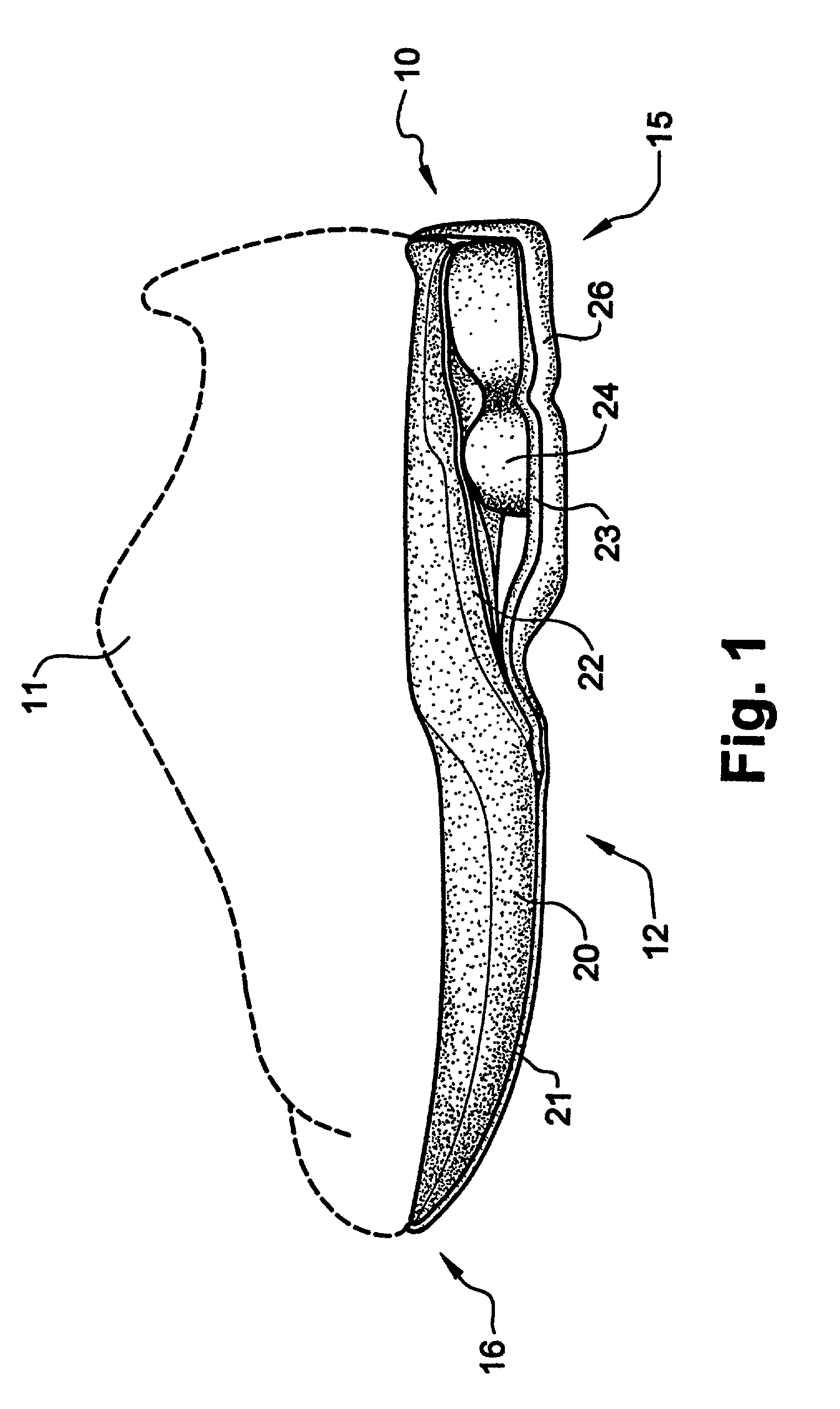
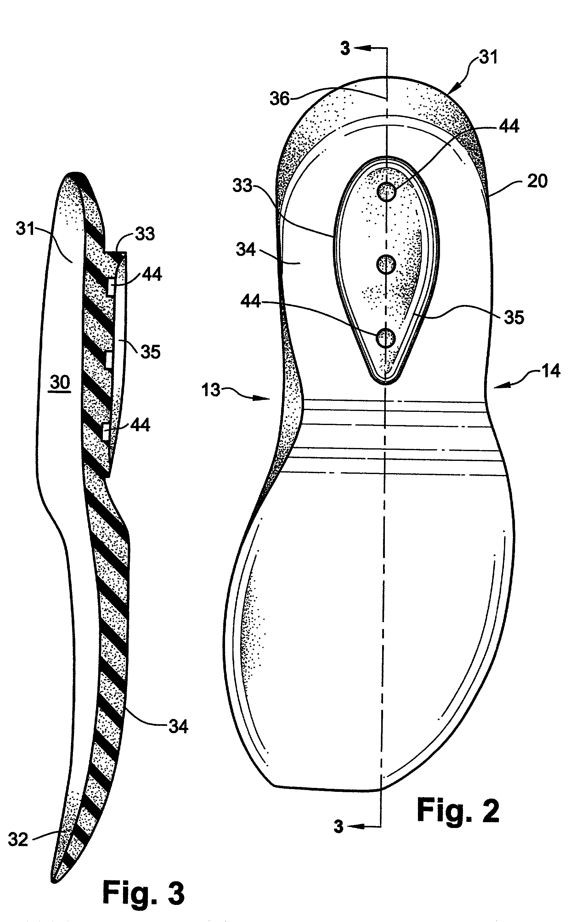
[0046] An understanding of the preferred embodiment of the present invention can be best gained by reference to FIG. 1 which illustrates the medial side of a shoe for use on the right foot of a user. The left shoe incorporating the present invention would be a mirror image of that shown in FIG. 1. A shoe 10 is shown having an upper 11 and a sole 12. Shoe 10 includes a medial side 13 and a lateral side 14, a heel region 15 and a forefoot region 16. The upper 11 used in conjunction with the present invention may be any conventional shoe upper, including an upper as might be found in an athletic shoe. Although the description of the present invention is directed toward athletic shoes, such as shoes used for running, basketball, aerobics and the like, it is understood the present invention may be incorporated into street shoes or boots such as hiking boots. Upper 11 may be attached to sole 12 in any conventional manner.

[0047] Sole 12 is formed of several components including a midsole 2...


PUM


Abstract

The invention is directed to a midsole assembly for footwear which includes medial and lateral unsymmetrical stabilizing pods disposed between shock absorbing upper and lower deflectable plates positioned at the heel portion of the midsole. The bottom surface of the heel portion of the midsole includes an axially aligned deflection platform defined by a concave surface. The upper shock absorption plate is disposed adjacent the bottom surface of the midsole and includes an aperture therethrough which is adapted to receive the deflection platform. The bottom plate includes a deflectable concave segment which is aligned with and adapted to engage the deflection platform of the midsole and be urged downwardly upon the imposition of force upon the midsole by the user's foot. The medial and lateral stabilizing pods are mounted between the upper and lower plates along the medial and lateral sides of the heel portion of the midsole and are respectively adapted to dynamically respond to the forces imposed on the medial and lateral sides of the heel. To control pronation and supination of the shoe and user's foot, the hardness of the medial stabilizing pod may be greater than that of the lateral stabilizing pod.

Description

[0001] This application is a continuation-in-part of Applicant's co-pending application Ser. No. 09 / 967,589 filed Sep. 28, 2001 and entitled Shoe Incorporating Improved Shock Absorption and Stabilizing Elements, which application is now pending.[0002] 1. Field of the Invention[0003] The present invention generally relates to footwear construction and in particular to the use of multiple shock absorption and stabilizing members incorporated into the heel portion of the midsole of the footwear.[0004] 2. Prior Art[0005] The result of the increased popularity of exercise, as well as the necessities of everyday walking and standing, it has been recognized there is a need to alleviate and relieve the stress imposed on a person's feet and legs. In particular, it is essential that shoes and other like footwear provide for suitable shock absorption and stability. This is particularly important where the shoes or footwear are to be used inactive pursuits such as running or other athletic ende...

Claims


Application Information

Patent Timeline
IPC IPC(8): A43B13/14A43B13/18
CPCA43B13/143A43B13/145A43B13/187A43B13/181A43B13/146
Inventor TURNER, JEROME A.
Owner SEQUENTIAL AVIA HLDG LLC
Learn More