
Digital video signal interface module for transferring signals to a long distance

a technology of video signal and interface module, which is applied in the field of video cable, can solve the problems of high production cost, system complexity, and inability to transfer digital signals

Inactive Publication Date: 2003-02-20
OPHIT
View PDF4 Cites 76 Cited by
  • Summary
  • Abstract
  • Description
  • Claims
  • Application Information

AI Technical Summary

Problems solved by technology

But, there is a problem that the digital signals cannot be transferred because a frequency of a digital interface type is a high frequency of hundreds MHz to several GHz.
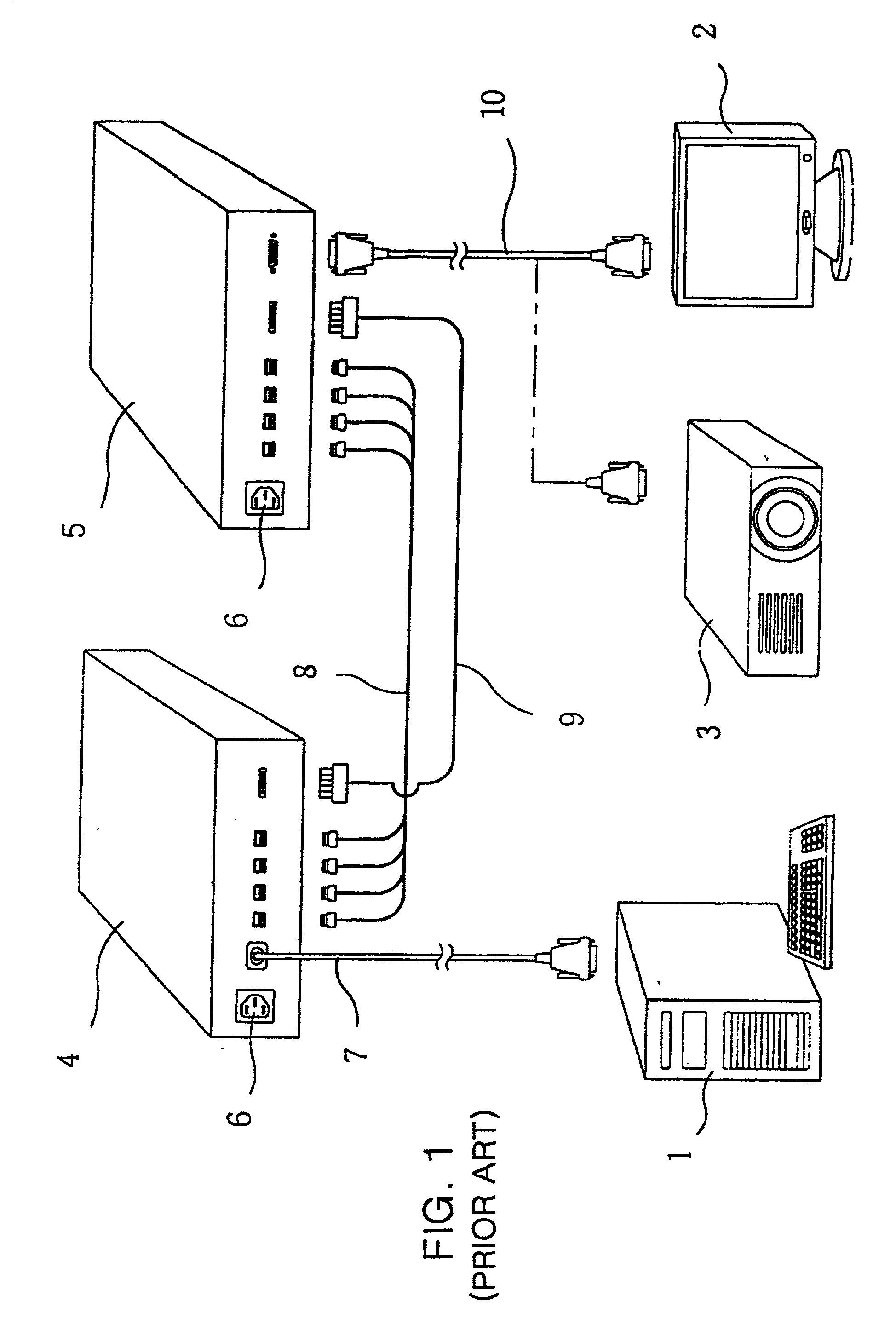
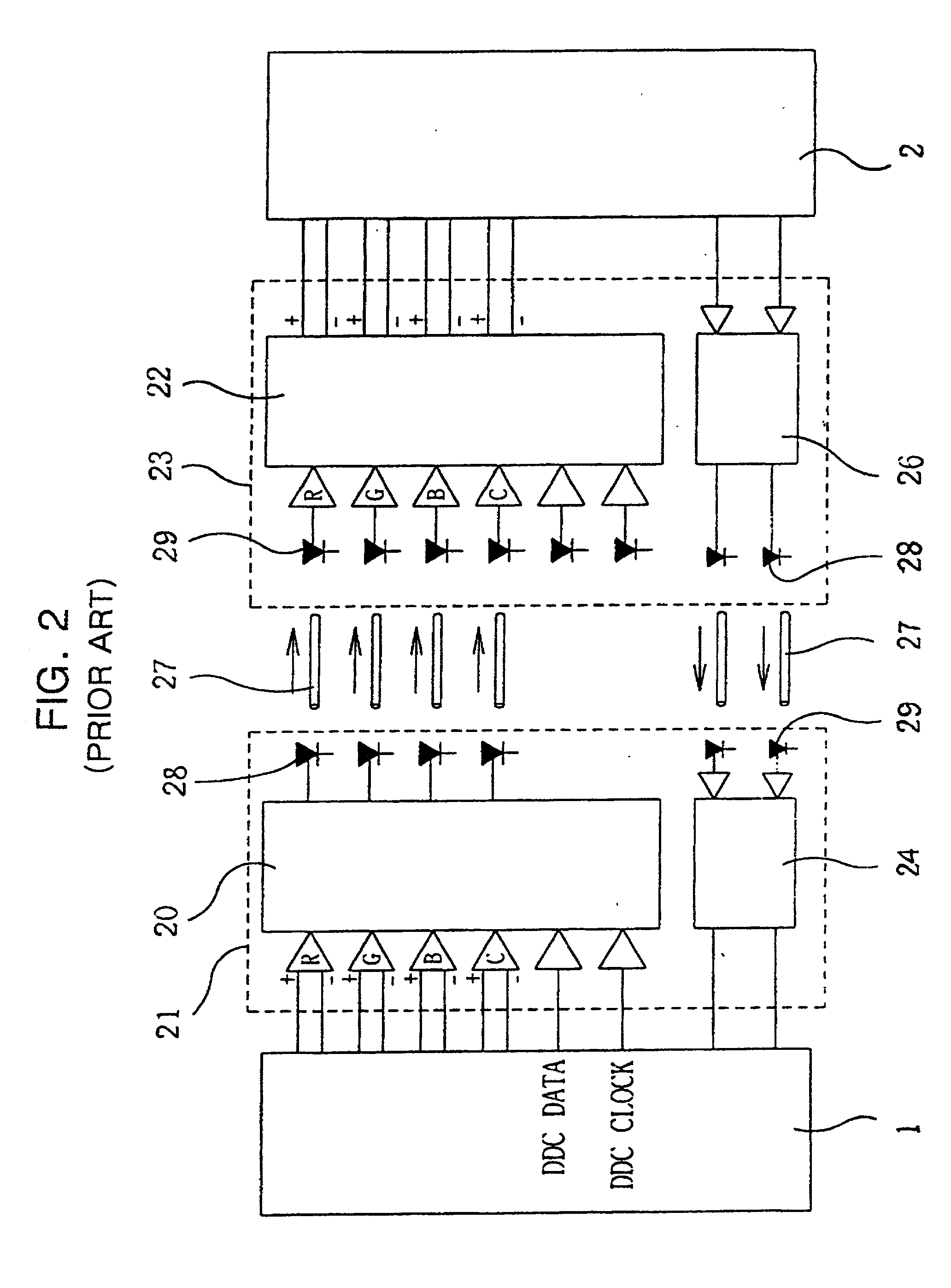
However, there are problems that the amplifier (4) and the receiver (5) of the conventional system require the external power supply (6), two digital exclusive use lines (7, 10), four BNC lines (8), and a complex DDC line (9), the system is complexed, and a production cost is high because the components are many, and an installation is inconvenient, etc.
The production cost becomes raised and a transferring velocity of the DDC signal is too late to transfer the optic signal because of a low frequency of 100 kHz.
The HPD function is operated by detecting a DC +5 V, but the above cited system cannot support the HPD function.
However, the method becomes more complicated in a structure of the system and the production cost becomes raised.
The extra problem is that the power supply must be supplied from the outsides in order to operate functional devices of the receiver because the extra pins do not exist in order to supply the power supply from the monitor in the receiver under DVI, DFP, or Low Voltage Differential Signalling (LVDS) of the digital interface standards.

Method used


Image

  • Digital video signal interface module for transferring signals to a long distance
  • Digital video signal interface module for transferring signals to a long distance
  • Digital video signal interface module for transferring signals to a long distance

Examples


Embodiment Construction

[0034] Reference will now be made in detail to a preferred embodiment of the present invention, example of which is illustrated in the accompanying drawings.

[0035] A "long distance" is defined as about 5 to hundreds meters between a computer body and a monitor in the present invention.

[0036] FIG. 3 is a perspective drawing illustrating a digital video signal interface module that is able to transfer signals to a long distance according to a preferred embodiment of the present invention.

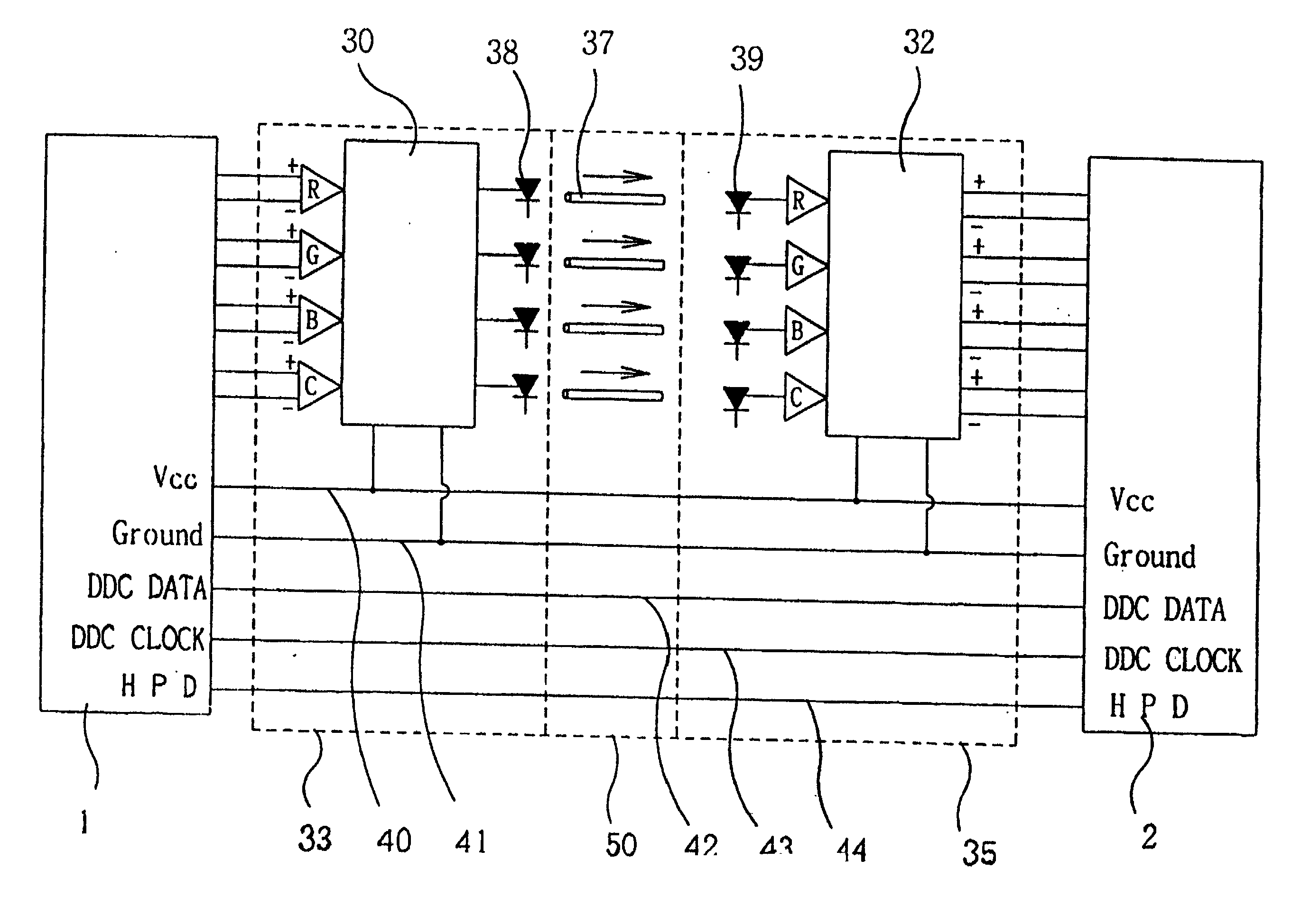
[0037] As shown in FIG. 3, a transferring connector (33) for a computer (1) and a receiving connector (35) for a monitor are installed in both terminals of cables (50, 60, 70) having length of about 10 to hundreds meters.

[0038] Table 1 represents a detail information of each pins used in the connectors (33, 35).

1TABLE 1 Pin No. Signal Pin No. Signal Pin No. Signal 1 TMDS data 9 TMDS data 17 TMDS data 0- 2- 1-2 TMDS data 10 TMDS data 18 TMDS DATA 2+ 1+ 0+ 3 TMDS data 11 TMDS 19 TMDS data {fraction (2 / 4...


PUM


Abstract

The present invention discloses a digital video signal interface module that enables a distance between a computer having a digital video output and a monitor having a digital video input to length and comprises a laser driver and a laser diode receiving digital video signals of Red (R), Green (G), Blue (B), Clock (C) outputted from a computer and converting the signals to a laser singals, respectively; a photodiode (PD) receiving the respective laser signals and restoring to electric signals; a photodiode amplifier amplifying the signals of the photodiode and transferring the signals to a Liquid Crystal Display (LCD) monitor; a plurality of an optic fiber installed between the respective laser diode and the respective phoptodiode and transferring the laser signals; and a power supply line and a ground voltage line installed between the computer and the LCD monitor along the optic fibers and supplying a power voltge to the laser driver and the PD amplifier.

Description

CROSS REFERENCE[0001] This application claims the benefit of Korean Patent Application No. 2001-29271, filed on May 26, 2001, under 35 U.S.C. .sctn. 119, the entirety of which is hereby incorporated by reference.[0002] 1. Field of the Invention[0003] The present invention relates to a video cable between a computer and monitor, more particularly, to a digital video signal interface module that is able to lengthen a transferring distance of a computer outputting a digital video output and a monitor inputting a digital video input.[0004] 2. Description of Related Art[0005] The video signal outputted from a conventional computer is an analog type or a digital type. The analog type is generally applied to a conventional cathode ray tube (CRT) type and the digital type is generally applied to the monitors such as a liquid crystal display (LCD). Accordingly, A-D converter is used when the LCD monitor is used for the computer outputting the analog video output.[0006] However, many computer...

Claims


Application Information

Patent Timeline
IPC IPC(8): G06F3/153H04B10/00G06F13/00H04N7/22
CPCH04N7/22G06F13/00
Inventor MOON, JONG-KOOKKWAK, JONG-DO
Owner OPHIT
Learn More