
Dial for timepiece, manufacturing method thereof and timepiece

a manufacturing method and timepiece technology, applied in the field of timepiece dials, timepiece manufacturing methods and timepieces, can solve the problems of dial appearance, dial darkening, and incongruity of appearance,

Inactive Publication Date: 2003-01-09
CASIO COMPUTER CO LTD
View PDF0 Cites 13 Cited by
  • Summary
  • Abstract
  • Description
  • Claims
  • Application Information

AI Technical Summary

Benefits of technology

[0009] According to the invention, the cross-sectional area of the lower-side holes of the through holes is larger than the cross-sectional area of the upper-side holes. Therefore, the upper-side holes can be formed to be so small that the through holes are discreet from above, when the decoration member is used for a dial. As a result, the dial can have a good showing. Furthermore, it is possible to sufficiently take in light from the luminescent member through the lower-side holes. Therefore, even if the diameter of the upper-side holes is small, the enough amount of light can pass through the through holes to obtain the sufficient intensity of illumination. As a result, the upper portion of the decoration member can be illuminated brightly.

Problems solved by technology

One problem encountered in such a dial is the through holes.
If the diameter of the through holes is small, the light from the luminescent member cannot pass through them enough to illuminate the dial, so that the dial becomes dark.
On the other hand, the through holes with a large diameter become so visible that the appearance of the dial leads sense of incongruity.

Method used


Image

  • Dial for timepiece, manufacturing method thereof and timepiece
  • Dial for timepiece, manufacturing method thereof and timepiece
  • Dial for timepiece, manufacturing method thereof and timepiece

Examples


first embodiment

[0026] First Embodiment

[0027] Hereinafter, a first embodiment of the present invention applied to a wristwatch will be explained, with reference to FIG. 1 to FIGS. 3A to 3D.

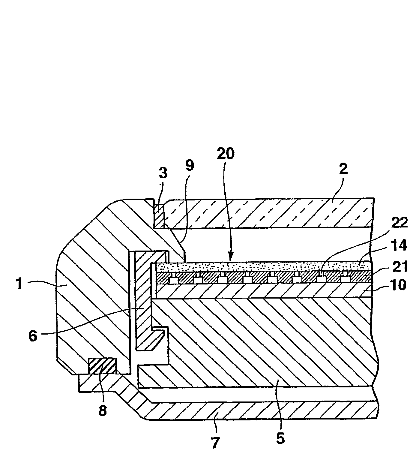
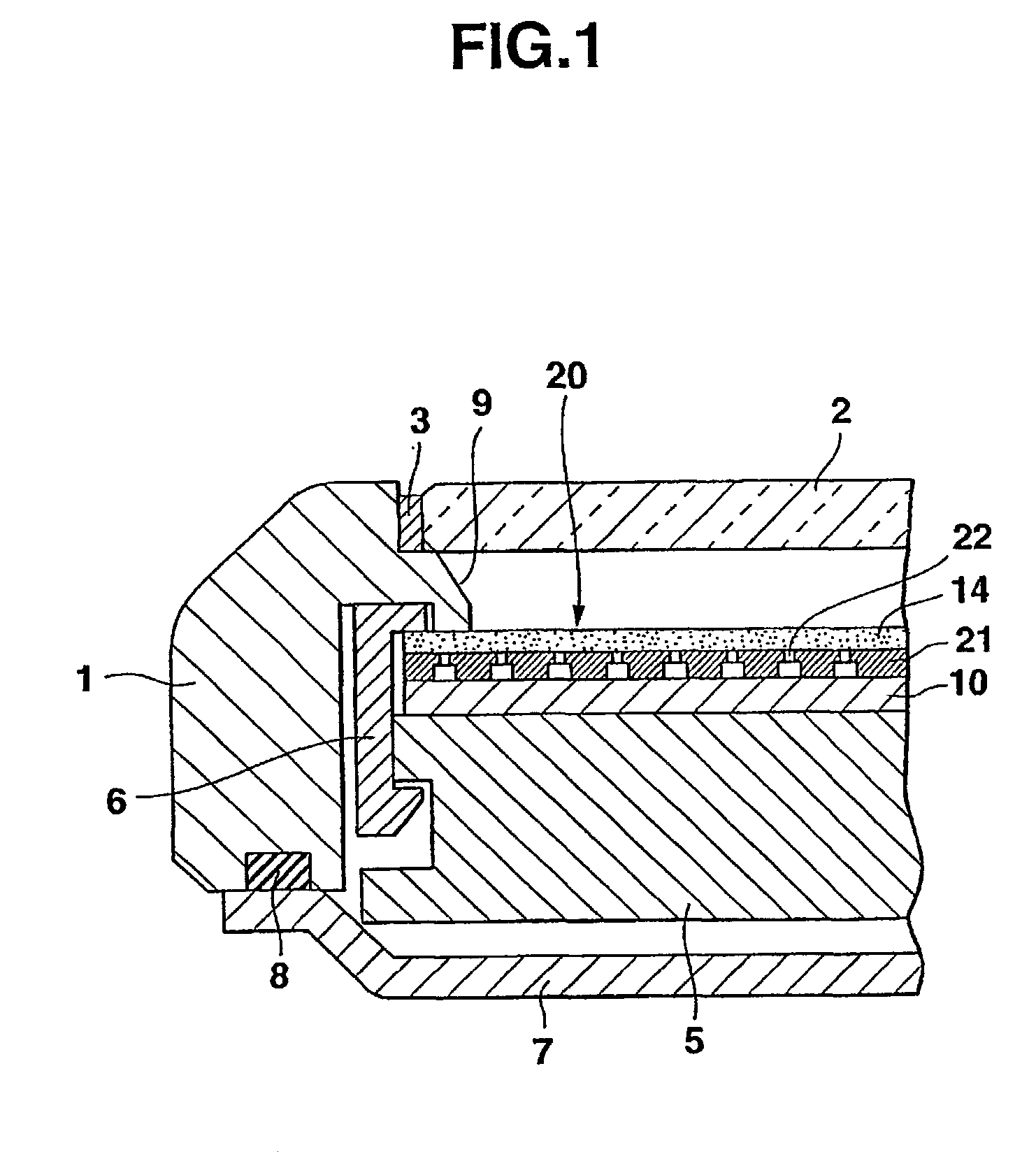
[0028] FIG. 1 is an enlarged cross-sectional view of the principal portion showing the inner structure of the wristwatch. The wristwatch comprises a case complete 1. A watch glass 2 is mounted on the case complete 1 with a packing 3 between them. A dial 20 for a timepiece and a watch module 5 that are attached to a movement holder 6 are incorporated inside the case complete 1. Moreover, a case back 7 is attached to the bottom of the case complete 1 with a waterproof ring 8 between them.

[0029] The watch module 5 has an analogue function and may have a digital function. The watch module 5 is designed to make hands (not shown) move above the dial 20. A dial cover 9 covering the top of the movement folder 6 and fitted on the periphery of the dial 20 is provided inside the case complete 1 to protrude inward.

[0030] The...

second embodiment

[0042] Second Embodiment

[0043] Next, a second embodiment of the present invention applied to a wristwatch will be explained with reference to FIG. 8 and FIGS. 9A to 9D. In these figures, the same reference numerals are attached to the same portions as the first embodiment shown in FIG. 1 to FIGS. 3A to 3D.

[0044] A dial 30 for a timepiece of the wristwatch has the same structure as the first embodiment except for the sizes and relationship of holes 33 placed at the upper side and holes 34 placed at the lower side of through holes 32 of a decoration member 31.

[0045] That is, as shown in FIG. 8, a plurality of the through holes 32 are formed in the decoration member 31 so that the cross-sectional area of the lower-side holes 34, formed in the substrate 15 for the decoration member, is larger than the cross-sectional area of the upper-side holes 33. Moreover, three upper-side holes 33 are formed to be within the area of a single lower-side hole 34. In this case, as shown in FIG. 8, the ...

third embodiment

[0054] Third Embodiment

[0055] Next, a third embodiment of the present invention applied to a wristwatch will be explained with reference to FIG. 12 to FIG. 14. In these figures, the same reference numerals are attached to the same portions as the first embodiment shown in FIG. 1 and FIGS. 3A to 3D.

[0056] According to a dial for the wristwatch, the densities of through holes of a decoration member 41 differ between at the center portion 42 and at the peripheral portion 43. The holes are formed at the center and the vertexes of an equilateral hexagon, while the lines of the holes are arranged at intervals of 0.45 mm, at the center portion 42, as shown in FIG. 13. The holes are formed in a line at intervals of 0.25 mm, and the lines of the holes are arranged alternatively, at the peripheral portion 43, as shown in FIG. 14. Thus, it is possible to enhance the decoration effect by making the densities of the holes differ between at the center portion and at the peripheral portion, like t...


PUM


Abstract

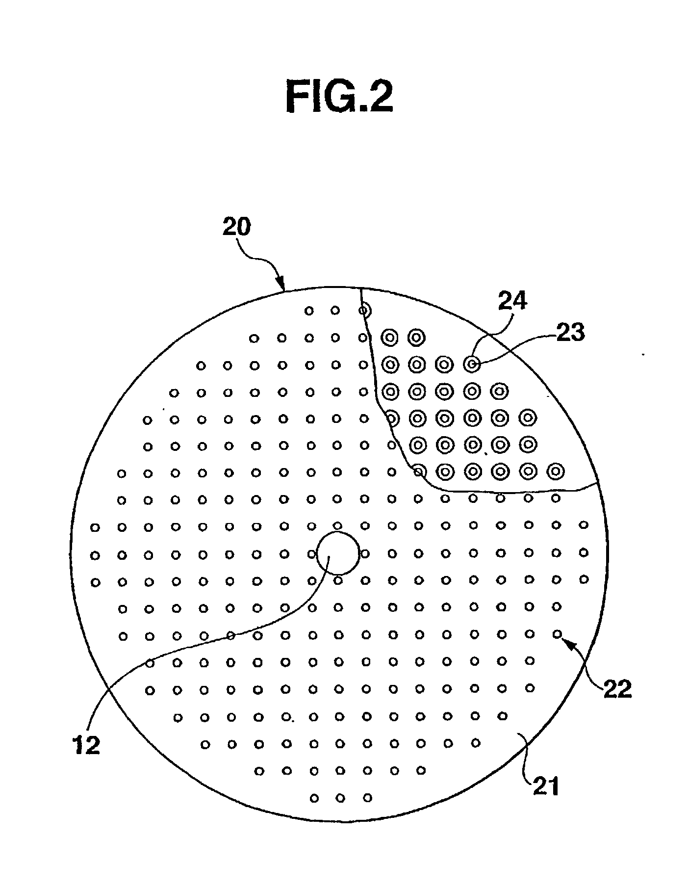
With a dial for a timepiece comprising a decoration member 21 having a plurality of through holes 22 formed vertically on a luminescent member 10, the cross-sectional area of lower-side holes 24 of the decoration member 21 is formed to be larger than that of upper-side holes 23. Therefore, even if a substrate is thick, the diameter of the upper-side holes 23 of the through holes 22 can be formed to be small sufficiently. Moreover, compared to a dial size 20 for a timepiece wherein the decoration member 21 is placed on the luminescent member 10, the diameter of the through holes 22 of the decoration member 21 is small. Thus, it is possible to take in enough light from the luminescent member 10 through the lower-side holes 24 to ensure the sufficient amount of light through the through holes 22. It is possible to obtain sufficient illuminance for the dial.

Description

[0001] 1. Field of the Invention[0002] The present invention relates to a dial for a timepiece, a manufacturing method thereof and a timepiece.[0003] 2. Description of the Related Art[0004] According to an earlier development, there is a dial for a timepiece, such as a wristwatch, comprising a luminescent member made of an EL element (Electro Luminescent element) for emitting light to enable users to recognize time even in a dark place.[0005] As this type of a dial for a timepiece, for example, there is one that comprises a decoration member having a plurality of through holes on a luminescent member so that the luminescent member emits light upwards through each of the through holes for illuminating the upper surface of the decoration member. There are U.S. Pat. Nos. 5,838,640, 5,930,204, 5,880,796 and 6,020,943 and U.S. patent application Ser. Nos. 09 / 323,449, 09 / 152,410 and 09 / 702,259, as earlier developments of the present invention.[0006] One problem encountered in such a dial ...

Claims


Application Information

Patent Timeline
Patent Type & Authority Applications(United States)
IPC IPC(8): G04B19/30G04B19/32G04B19/06G04B45/00G04C17/02G04D3/00G04G9/00
CPCG04B19/32G04B45/0015G04C17/02G04D3/0069G04G9/0041
Inventor AMANO, MASAOMINAMI, SHUNJI
Owner CASIO COMPUTER CO LTD
Learn More